20B FUEL SYSTEM
Fuel injection pump
To remove and to fit20B-05
To remove
Special tools:
Timing light, KJ37007
Piston position probe, PD.221
Puller, PD.155C
Adaptor for use with PD.155C, PD.155-B5
1Remove the rocker cover, operation 12A-01.
2 Loosen the setscrews which retain the
atomisers.
3 Rotate the crankshaft clockwise, from the front,
until the push rod for the inlet valve of number 1
cylinder just releases.
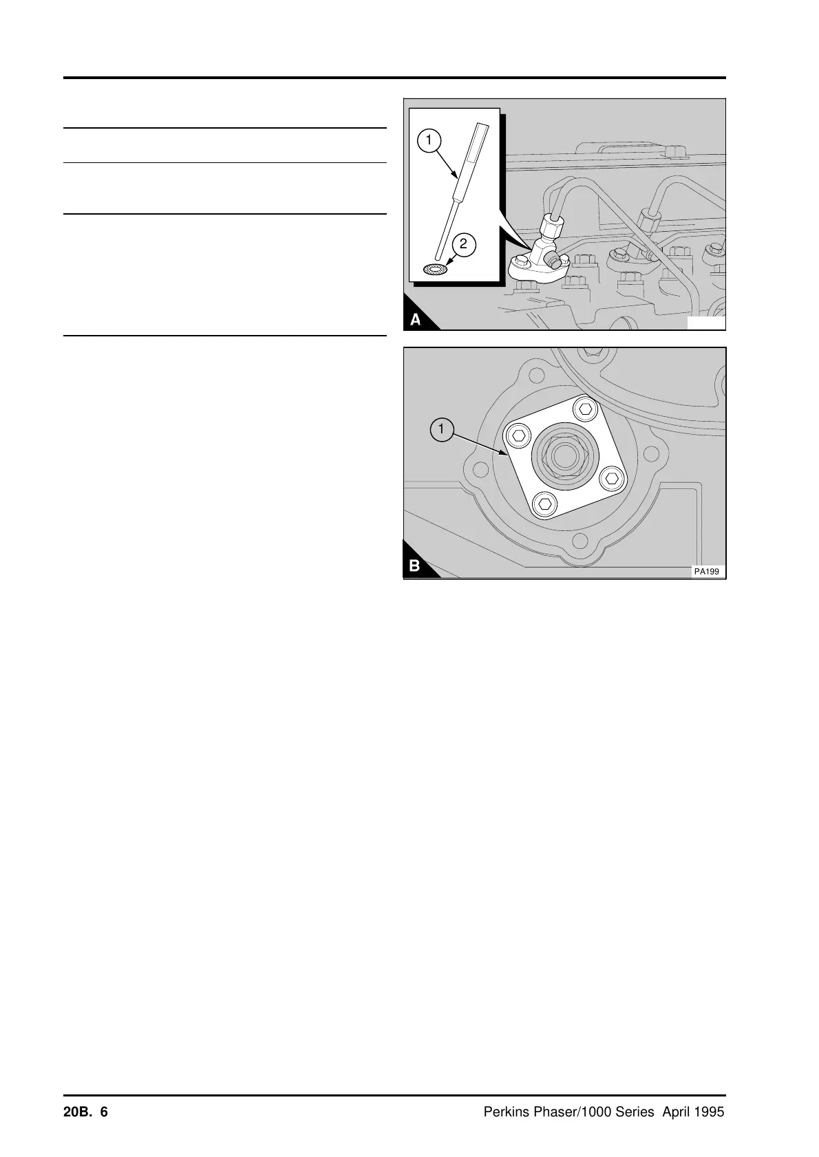
Note: A locally made washer (A2) must be fitted
onto the piston position probe (A1) when the engine
check angle is less than 100° BTDC. See the data
and dimensions for details.
4 Remove the atomiser from number 1 cylinder
together with its seat washer and put the piston
position probe, PD.221, (A1) in its place. Fit the
atomiser clamp to the probe and tighten the
setscrews gradually and evenly.
Caution: Ensure that the piston comes lightly into
contact with the piston position probe, or the piston
could be damaged. Also the probe could become
bent and this could cause the piston position to be
incorrect.
5 Very carefully turn the crankshaft clockwise until
the piston just comes into contact with the piston
position probe.
6 Release the setscrews and remove the gear
cover from the cover of the timing case.
7 Release the cap screws which retain the fuel
pump gear. Remove the cap screws and the plate
(B1). Ensure that when the cap screws are
removed, the plate does not fall into the timing
case.
PA257B
a
a
1
a
a
2
a
a
1
PA199
20B.06 Perkins Phaser/1000 Series, April 1995