19 LUBRICATION SYSTEM
To dismantle and to assemble19A-09
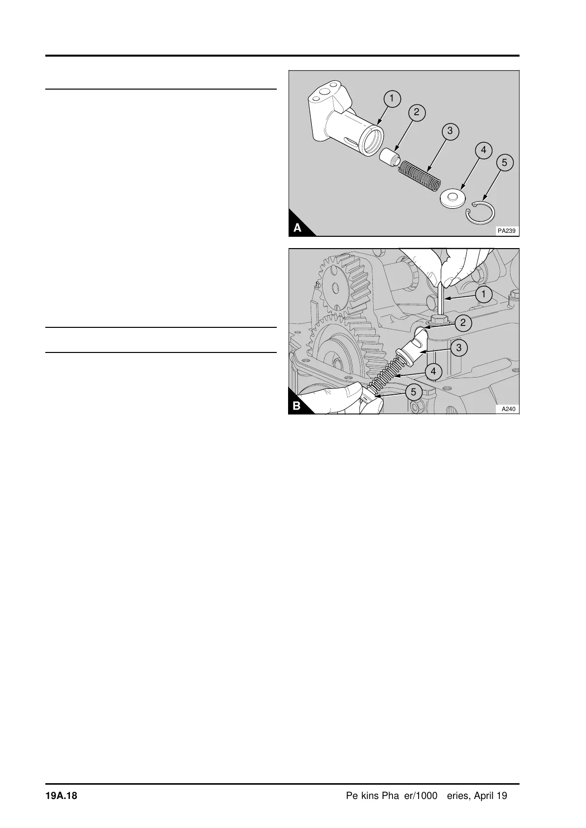
If necessary, the relief valve can be dismantled and
assembled while it is fitted to the engine.
1 Apply pressure to the end plate (A4 or B5) of the
spring assembly; release the circlip (A5) or remove
the pin (B1) and carefully release the pressure to
remove the end plate and the spring (A3 or B4)
from the valve body. Remove the plunger
(A2 or B3) from the bore of the body (A1 or B2).
2 Ensure that all the components are cleaned and
then lubricated lightly with clean engine lubricating
oil.
3 Fit the plunger into the bore with its hollow end
to the inside. Fit the spring and the end cap into the
bore with the ends of the spring fitted around the
bosses of the plunger and the end plate. Apply
pressure to the end plate and fit the circlip into its
groove or fit the pin into the holes in the balancer
frame.
To inspect19A-10
Do not try to change the operation pressure of the
relief valve by a method other than the installation
of new components.
1 Check the spring for wear and other damage
and, if possible, check the load necessary to
compress the spring to its fitted length, see the
data and dimensions.
2 Check the plunger for wear and other damage
and ensure that it slides easily in the bore of the
relief valve.
3 Check the body and the end plate for wear and
other damage.
4 Renew worn or damaged components.
a
a
a
1
a
a
2
3
4
a
a
a
5
PA239
1
a
a
2
a
a
a
3
a
a
4
a
a
5
PA240
19A.18 Perkins Phaser/1000 Series, April 1995