12 CYLINDER HEAD ASSEMBLY
Rocker assembly
To dismantle and to assemble12A-03
To dismantle
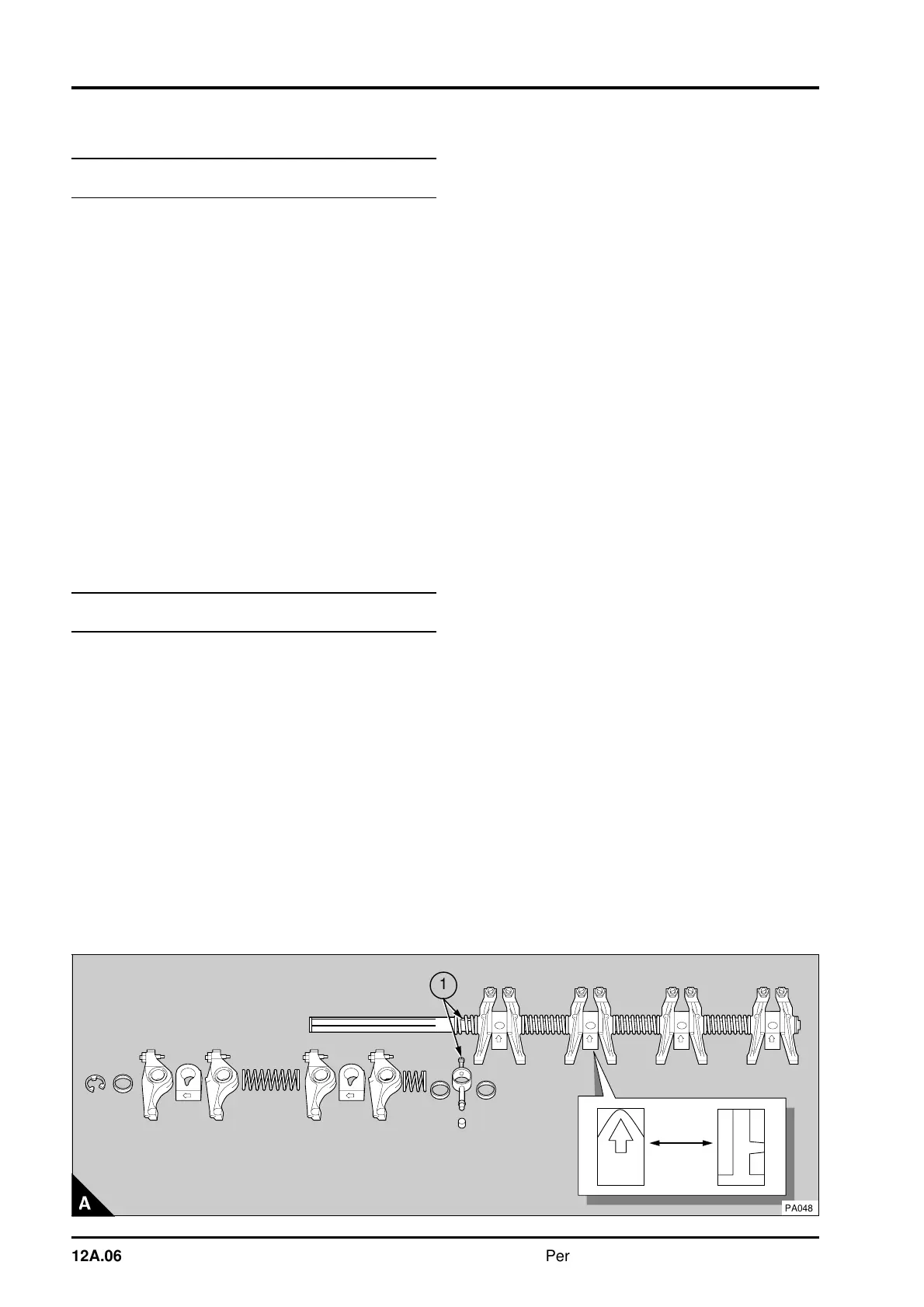
1 Remove the clips from both ends of the rocker
shaft. Ensure that the ends of the rocker shaft are
not damaged. Release the location screw (A1) for
the oil supply connection.
2 Dismantle the assembly and make a note of the
position of each component to ensure that they can
be assembled more easily.
To assemble
1 Ensure that the oil holes in the rocker shaft and
in the rocker levers are not restricted.
2 Lubricate the components with clean engine
lubricating oil before assembly. Assemble the
components in the correct order (A) and ensure
that the location screw (A1) for the oil supply
connection is fitted correctly in the rocker shaft. Fit
the clips to the ends of the rocker shaft.
To inspect and to correct12A-04
To inspect
1 Clean and inspect all the components for wear
and any other damage. Check the clearance of the
rocker levers on the rocker shaft. If the clearance is
larger than 0,13 mm (0.005 in), renew the rocker
lever bush and/or the rocker shaft.
To correct
1 To renew the rocker lever bush, press out the
old bush with a suitable mandrel.
2 Align the lubrication hole of the new bush on the
same side as the rocker lever lubrication hole and
press the bush into position.
3 Ream the bush in the rocker lever to give a
clearance on the rocker shaft of 0,03/0,09 mm
(0.001/0.004 in). Clean thoroughly the bush and
check that the oil hole is free from debris.
Note: The rocker levers used on some low rated
engines do not have bushes.
a
a
a
12A.06 Perkins Phaser/1000 Series, April 1995