19 LUBRICATION SYSTEM
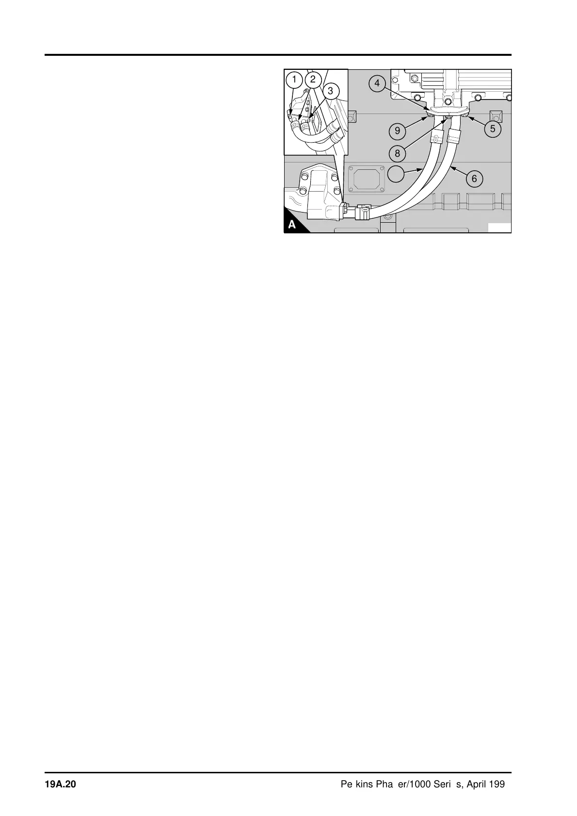
To fit the pipes - arrangement 2
1 Put a setscrew (A5) in position in the flange of
the inner oil cooler pipe (A6), part number
2483A004. Put a new joint (A4) in position on the
setscrew. Hold the flange and the joint in position
and fit the centre setscrew (A8). Tighten the
setscrews finger tight.
2 Put the outer pipe (A7), part number 2483A003,
in position on the flange of the oil cooler and fit the
third setscrew (A9) finger tight. Beginning with the
centre setscrew, tighten the three setscrews to 22
Nm (16 lbf ft) 2,2 kgf m.
3 Put a setscrew (A3) in position in the flange of
the inner pipe for the oil filter head. Put a new joint
in position on the setscrew. Hold the flange and the
joint in position and fit the centre setscrew (A2).
Tighten the setscrew finger tight.
4 Put the flange of the outer pipe in position and fit
the third setscrew (A1), tighten it finger tight.
Beginning with the centre setscrew, tighten the
three setscrews to 22 Nm (16 lbf ft) 2,2 kgf m.
To Inspect
1 Remove any old pieces of the joint and clean the
flange faces of the oil pipes.
2 Thoroughly clean the oil pipes in an approved
detergent cleaning solution.
3 Check the outer cover of the pipes for signs of
leakage, cracks or splits. If the outer cover or the
flanges are damaged the pipe must be renewed.
PA305
1
2
3
a
a
4
a
a
5
a
a
a
6
9
8
a
a
7
19A.20 Perkins Phaser/1000 Series, April 1995