20D FUEL SYSTEM
Lucas DP 200 Series fuel injection
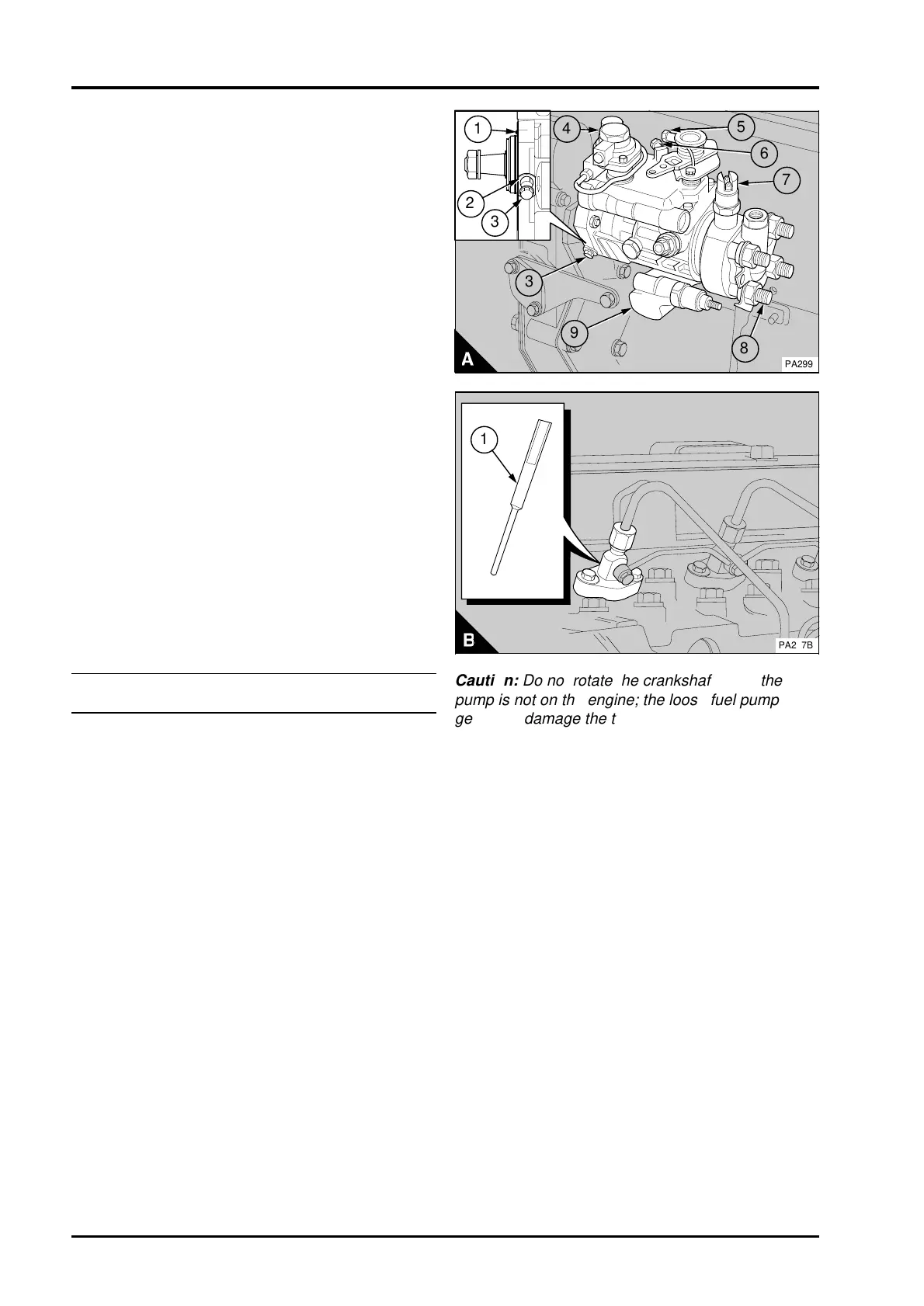
pump
These pumps have a locking screw (A3) and a
spacer (A2). The locking screw prevents the
rotation of the drive shaft when the pump is
removed from the engine.
An "O" ring (A1) is fitted in a groove in the pump
flange. This "O" ring is fitted instead of a joint
between the pump flange and the timing case.
Caution: The drive shaft of the pump must not be
rotated without the spacer in position under the
locking screw. If the drive shaft is rotated, the drive
shaft will be damaged.
Engines with these pumps have a timing mark on
the pump flange but not on the timing case.
For four cylinder engines: The high-pressure outlet
for number 1 cylinder is shown at (A8).
A new pump will be received locked at the correct
angle for the engine. It is important that the engine
number is given to the distributor when a new pump
is needed.
These engines operate with the timing of the fuel
injection retarded, therefore the accuracy
necessary to position the piston for timing is difficult
to obtain. Greater accuracy is possible if the piston
is further down the cylinder bore. A piston position
probe (B1), tool PD.122A, is used to set accurately
the piston at 100° BTDC.
To remove and to fit20D-06
To remove
1 Remove the rocker cover.
2 Loosen the setscrews which retain the
atomisers.
3 Rotate the crankshaft clockwise, from the front,
until the push rod for the inlet valve of number 1
cylinder just releases.
4 Remove the atomiser together with its seat
washer from number 1 cylinder and fit the piston
position probe, PD.221 (B1) instead. Fit the
atomiser clamp to the probe and tighten the
setscrews gradually and evenly to 12 Nm (9 lbf ft)
1,2 kgf m.
Caution: Ensure that the piston comes lightly into
contact with the piston position probe, or both the
piston and the probe could be damaged.
5 Slowly rotate the crankshaft clockwise, from the
front, until the piston just comes into contact with
the piston position probe. The piston will now be
set at 100° BTDC on the compression stroke of
number 1 cylinder.
3
2
1
4
a
a
5
PA299
8
a
a
9
3
7
a
a
6
PA257B
a
a
1
Caution: Do not rotate the crankshaft when the
pump is not on the engine; the loose fuel pump
gear may damage the timing case. If it is necessary
to rotate the crankshaft, fit the fuel pump temporarily
to ensure that the gear is in the correct position. If
the fuel pump is fitted temporarily in order to rotate
the crankshaft, the locking screw must be released.
20D.02 Perkins Phaser/1000 Series, April 1995