FUEL SYSTEM 20D
Note: The fuel pump can be removed from the
engine and fitted again if:
• The crankshaft is not rotated
• The drive shaft of the fuel pump is not rotated
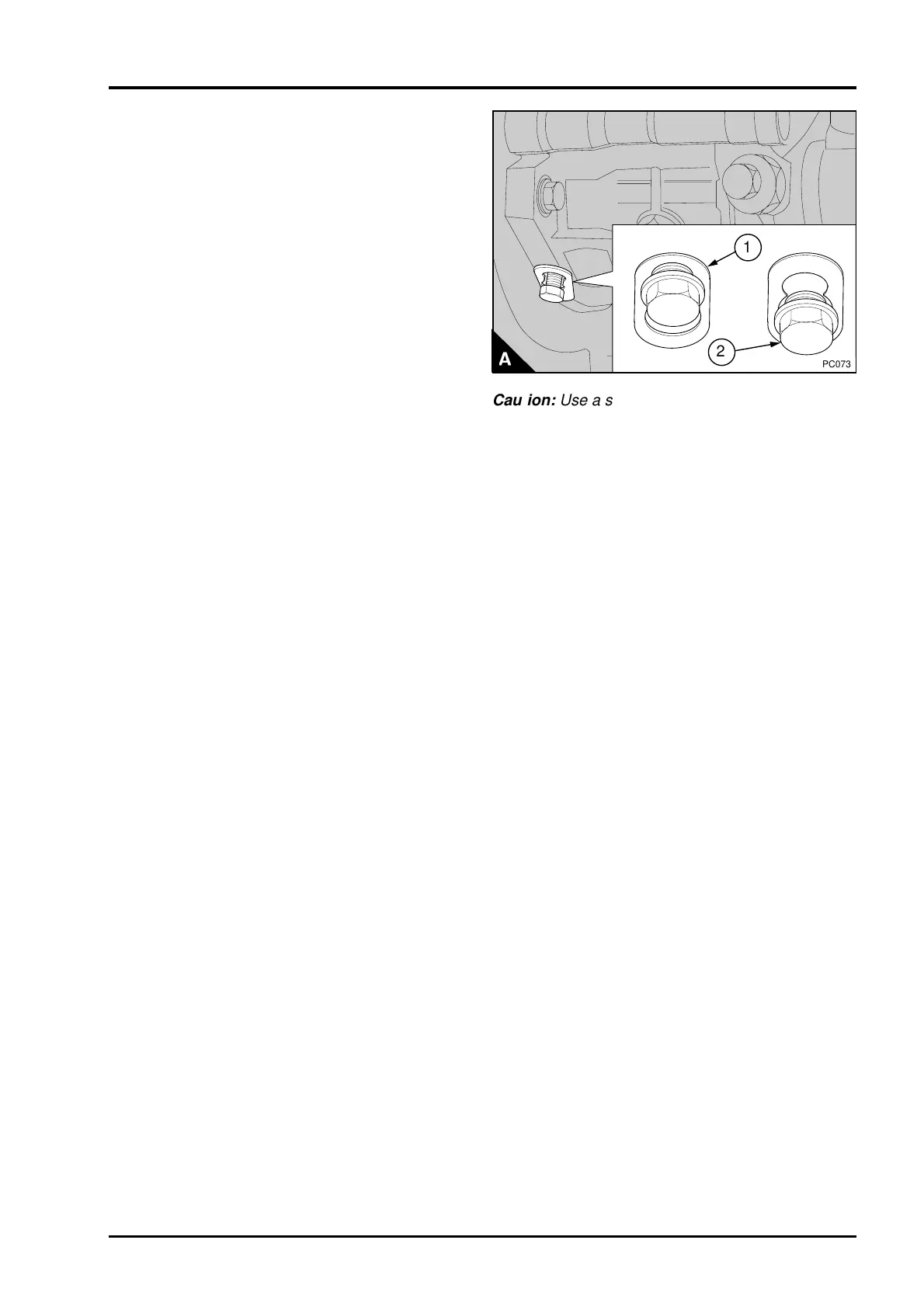
Caution:
If the crankshaft or the pump shaft is
rotated when the pump is off the engine. Or if the
engine timing is not correct the timing of the fuel
injection pump must be checked, operation 17D-03.
6 Release the locking screw and adjust the
spacer (A1) to enable the locking screw (A2) to be
tightened on the drive shaft of the fuel pump.
Tighten the locking screw to 12 Nm (9 lbf ft)
1,2 kgf m. Check that the spacer is free to move.
The drive shaft of the fuel pump is now
fastened.
Caution: Use a second spanner to prevent
movement of the high-pressure outlet when the
union nut for each high-pressure pipe is released.
7 Remove the pipes, the cables and the
connections for the cold start device and the
electrical stop solenoid from the fuel pump. Loosen
the nuts on the pump flange.
8 Release the setscrews and remove the gear
cover from the timing case cover. Release the nut
which retains the drive gear of the pump one to two
turns.
9 Fit the gear puller PD.155C and loosen the gear
on the drive shaft of the pump. Remove the puller,
nut and spring washer.
10 Remove the nuts from the flange of the fuel
pump and remove the pump.
To fit
1 Inspect the "O" ring and, if necessary, fit a new
"O" ring.
2 Lightly lubricate the "O" ring with clean engine
lubricating oil and put the pump into position on the
timing case. Ensure that the key is engaged
correctly in the keyway of the drive gear.
3 Fit the spring washer and the nut to retain the
drive gear. Tighten the nut to approximately 15 Nm
(11 lbf ft) 1,5 kgf m.
4 Hold the top of the pump toward the engine to
remove the backlash and fit the nuts to the pump
flange. Tighten them to 22 Nm (16 lbf ft) 2,2 kgf m.
5 Release the locking screw on the pump and
adjust the spacer (A1) to prevent the locking screw
(A2) from locking the pump shaft, tighten the
locking screw to 12 Nm (9 lbf ft) 1,2 kgf m. Check
that the spacer cannot move. The drive shaft of
the fuel pump is now free to move.
6 Fully tighten the nut for the drive gear to 80 Nm
(59 lbf ft) 8,2 kgf m. Fit the gear cover.
2
a
a
1
PC073
Caution: Use a second spanner to prevent
movement of the high-pressure outlet when the
union nut for each high-pressure pipe is tightened.
7 Fit the pipes, cables and connection for the cold
start device and electrical stop solenoid to the
pump.
8 Remove the piston position probe and fit the
atomiser together with a new seat washer. Tighten
the setscrews of all of the atomisers gradually and
evenly to 12 Nm (9 lbf ft) 1,2 kgf m.
9Eliminate air from the fuel system, operation
20D-08.
10 Fit the cylinder head rocker cover.
11
Operate the engine and check for leakage. With the
engine at the normal temperature of operation,
check that the idle speed and the maximum no load
speed are correct, operation 20D-07.
Perkins Phaser/1000 Series, April 1995 20D.03