17B ENGINE TIMING
General description
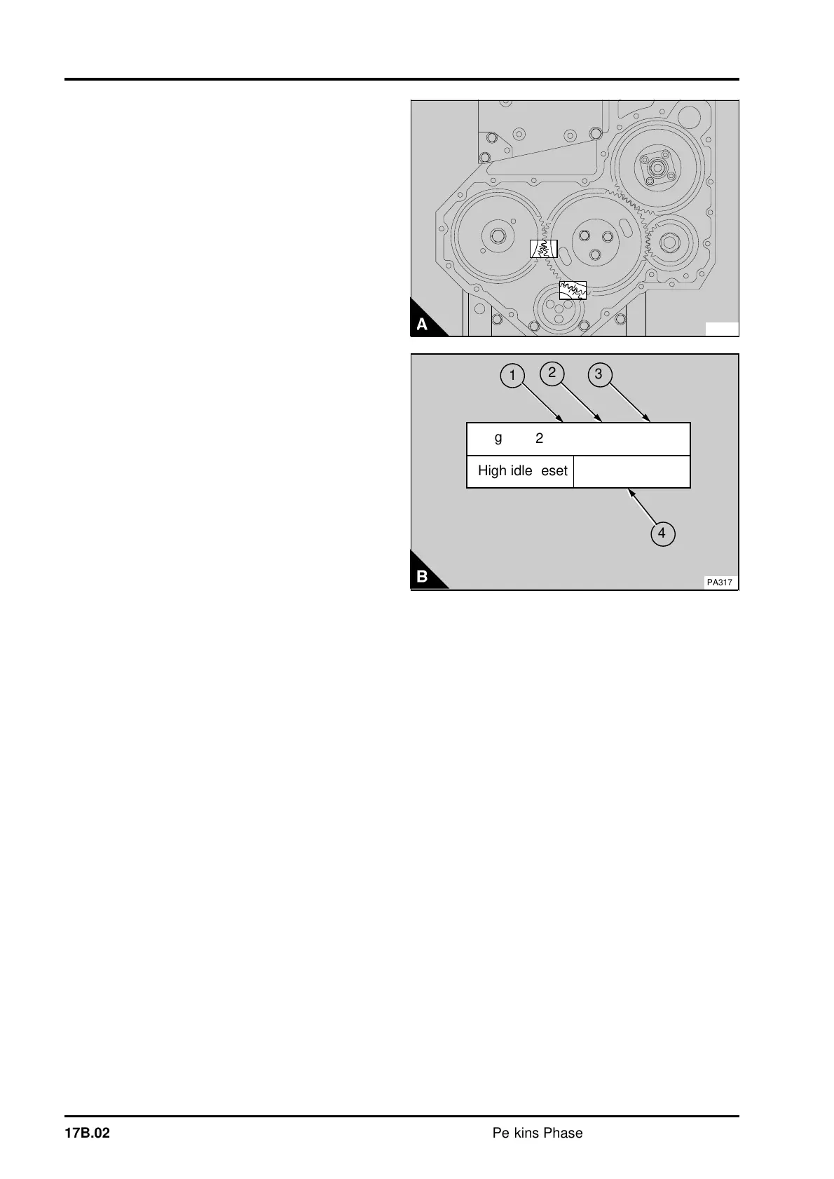
The timing gears are stamped with timing marks to
ensure that they are assembled correctly (A). The
stamped teeth of the crankshaft and camshaft
gears will be in mesh with the idler gear when
number 1 piston is at top dead centre (TDC) on the
compression stroke. The marked teeth of the idler
gear may not necessarily be in mesh, in this
position, because of the different speeds at which
the gears rotate.
There are no timing marks on the fuel pump gear of
engine types AE and YE. The gear, which is
fastened to a hub on the drive shaft of the fuel
injection pump, has slots to allow adjustment to the
timing.
A data plate is fitted to the pump. An example of
the information shown on the plate (B) is:
Perkins part number (1)
Fuel pump code (2)
Maximum engine no load speed (3)
High idle reset speed (4)
Notes:
• The maximum no load speed (B3) set by Perkins
may be reset by the equipment manufacturer. If the
speed is changed the new speed is shown in the
high idle reset position (B4). The original maximum
no load speed should be remove from the label.
• The adjustment screw for the maximum no load
speed, is sealed by the manufacturer. The setting
must not be changed, unless approved, as it could
affect the warranty of the engine.
For details of the fuel pump code for the engine see
the data and dimensions at the end of this section.
PA209
a
a
3
a
a
1
High idle reset
PA317
a
a
2
4
2643J000WM/1/2860
Mfg
17B.02 Perkins Phaser/1000 Series, April 1995