21 COOLING SYSTEM
Thermostats
Identification of the thermostat is by the nominal
temperature which is stamped on the by-pass valve
of the thermostat.
To remove, to fit and to test 21A-01
To remove
1 Drain the coolant level in the cooling system to
below the thermostat position and disconnect the
top hose from the coolant outlet connection.
2 Release the setscrews and remove the coolant
outlet connection.
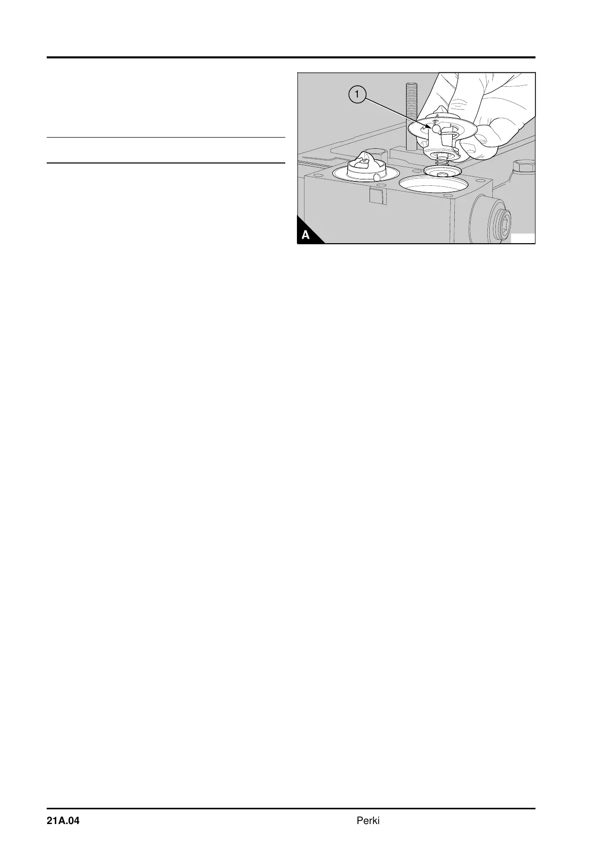
3 Remove the thermostat(s) (A).
To fit
1 Ensure that the joint faces of the housing and
the outlet are clean and that the jiggle pin(s) (A1) in
the thermostat(s) is/are free to move.
2 Put the new thermostat(s) in position in the
housing.
3 Fit a new joint and the coolant outlet connection.
Tighten the setscrews.
4 Connect the top hose and fill the cooling system.
To test
1 Hang the thermostat in a suitable container filled
with coolant.
2 Heat the coolant gradually. Use a thermometer to
check the temperature at which the valve starts to
open and at which it is fully open. The correct
temperatures are given in the data and dimensions.
Caution: If the thermostat does not operate
correctly, it must be renewed. Do not try to adjust
the settings.
PA267
a
a
1
21A.04 Perkins Phaser/1000 Series, April 1995