21 COOLING SYSTEM
Do not lubricate the seal. It is important that the
seal is not contaminated by oil or grease and if it is
held in the hand, it should be held by the edge of
the flange. Do not damage the ring of green sealant
applied to the body of the coolant seal just behind
the flange of the seal.
Support the pulley end of the shaft, ensure that
there are no sharp edges on the edge of the shaft
and put the seal into position on the end of the
shaft. Ensure that the ring of sealant is towards the
bearings. Use the tool to press the seal onto the
shaft until the bottom of the seal flange is in
complete contact with the pump body. Continue to
apply force for approximately ten seconds to ensure
that the seal remains in position when the force is
released.
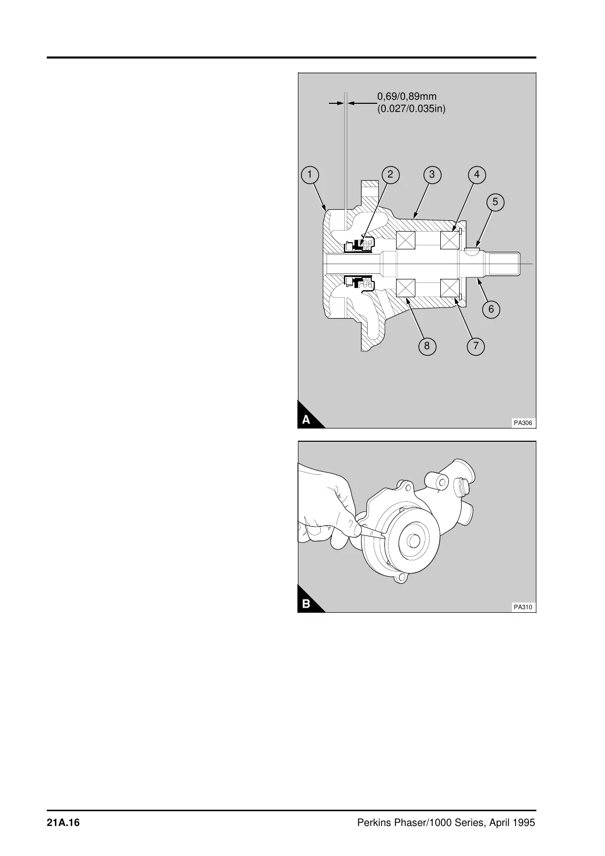
4 Support the pulley end of the shaft and press the
new impeller (A1) onto the shaft until the clearance
(A) between the impeller blades and the pump body
is 0,69/0,89 mm (0.027/0.035 in). The clearance
can be checked with a feeler gauge (B). The
minimum clearance with end float is 0,19 mm
(0.007 in).
Rotate the shaft to ensure that the impeller is free.
5Fit the coolant pump to the engine, operation
21A-03A.
a
a
a
a
a
a
a
a
a
a
a
a
a
a
a
a
a
a
a
a
a
a
a
a
a
a
a
a
a
a
a
a
a
a
a
a
a
a
a
a
a
a
a
a
a
a
a
a
a
a
a
a
a
a
a
a
a
a
a
a
a
a
a
a
a
a
a
a
a
a
a
a
a
a
a
a
a
a
a
a
a
a
a
a
a
0,69/0,89mm
(0.027/0.035in)
a
a
8
7
6
5
a
a
1
2
a
a
3
a
a
4
PA306
PA310
21A.16 Perkins Phaser/1000 Series, April 1995