24A AUXILIARY EQUIPMENT
To dismantle
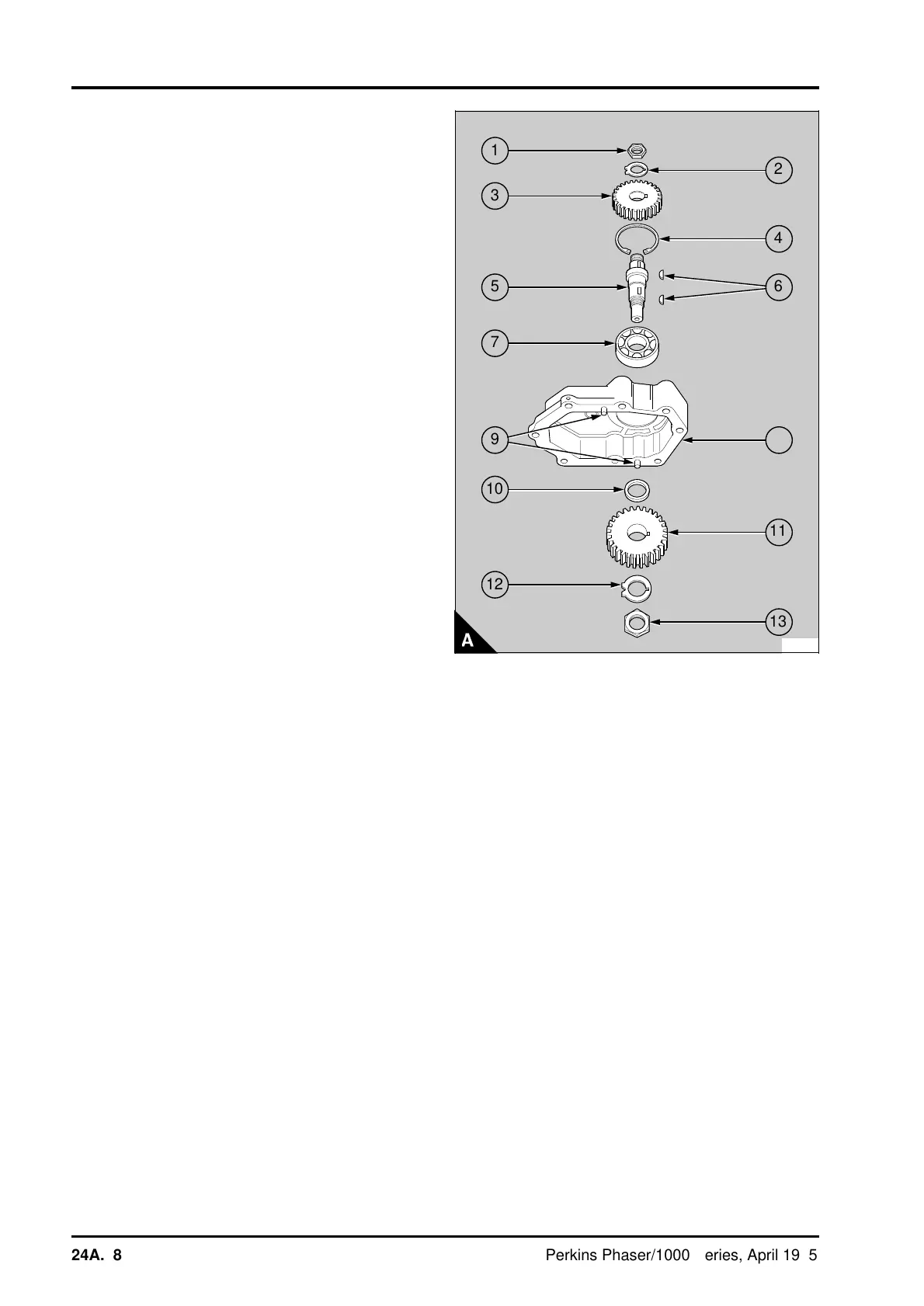
1 Release the tab washer (A2) from the nut (A1)
which is outside the housing (A8). Prevent
movement of the shaft (A5) and remove the nut.
Discard the tab washer. The latest drive assembly
does not use tab washers.
2 With a suitable puller, remove the gear (A3).
3 Release the circlip (A4) which retains the bearing
(A7).
4 Turn the housing upside down and release the
tab washer (A12) from the nut (A13) inside the
housing. Prevent movement of the shaft and
remove the nut. Discard the tab washer.
5 Provide a suitable support for the timing case
side of the housing. Protect the compressor end of
the shaft and press the shaft and bearing assembly
out through the timing case side of the housing.
To remove the bearing and shaft assembly
from the latest drive housing:
Provide a suitable support for the timing case side
of the housing. Heat the housing to a temperature
of 130°/140°C (266°/284°F); ensure that the
housing is heated evenly. Protect the compressor
end of the shaft and press the shaft and bearing
assembly out through the timing case side of the
housing.
6 Remove the gear (A11) from the housing.
7 Remove the keys (A6) and the spacer (A10) -
159 compressor only - from the shaft. A spacer is
not used in the latest drive assembly. With the
collar of the shaft towards the bottom, provide a
suitable support for the inner ball guide of the
bearing. Protect the end of the shaft and press the
shaft out of the bearing.
To assemble
1 Clean the components and check them for wear
or for damage, renew the components as
necessary.
2 Provide a suitable support for the inner ball guide
of the bearing (A7). Put a suitable adaptor on to the
collar of the shaft (A5) and press the shaft into the
bearing.
3 If necessary, remove the dowels (A9) from the
compressor flange of the housing (A8). Put the
housing with its compressor flange on a suitable
support that will allow enough space below the
housing for the shaft protrusion.
PA287
1
a
a
2
3
a
a
4
a
a
a
6
5
7
9
a
a
8
a
a
a
a
a
a
10
a
a
a
a
a
a
11
a
a
a
a
a
a
12
a
a
a
a
13
24A.08 Perkins Phaser/1000 Series, April 1995
 Loading...

