AUXILIARY EQUIPMENT 24A
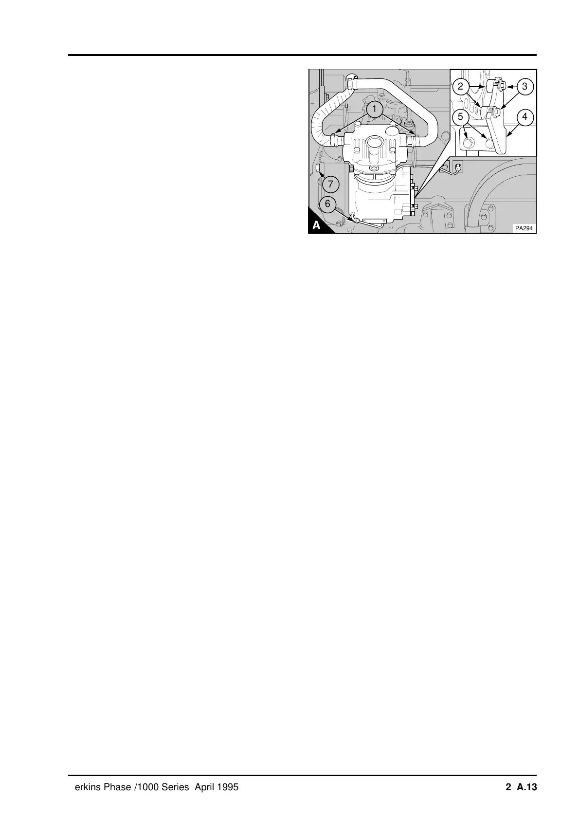
Caution: If the support bracket is mounted on the
oil filter head. Check that the nuts for the filter head
are tightened correctly before the compressor
support bracket is fitted.
8 Put the support bracket (A4) in position between
the cylinder block or the filter head and the
compressor. Loosely fit the fasteners (A5) the
spacer (A2), if fitted, and the setscrews (A3). Adjust
the support bracket to ensure that there will be no
tension on the compressor. Tighten the two
setscrews to 22 Nm (16 lbf ft) 2,2 kgf m for the
setscrews (A3) and 44 Nm (33 lbf ft) 4,5 kgf m for
the fasteners (A5).
Note: Spacers (A2) are used between the bracket
and the body of the 1W150R compressor.
9 Check that the "O" ring in the cover for the rear
of the compressor is not damaged. Fit the cover
and tighten the setscrews.
10 Ensure that there is no restriction in the oil pipe
(A6) between the engine and the compressor.
Before the oil pipe is connected to the compressor,
ensure that the engine stop solenoid is
disconnected or that the engine stop control is in
the 'stop' position. Operate the starter motor until a
free flow of oil comes from the oil pipe. Connect the
oil pipe. Connect the engine stop solenoid.
11 Connect the compressor coolant pipes (A1) and
the air pipes to the compressor.
12 Fill the engine cooling system. Operate the
engine and check for leakage of oil, coolant and air
from the compressor.
a
a
2
a
a
5
a
a
4
a
a
3
a
a
7
a
a
1
PA294
a
a
6
Perkins Phaser/1000 Series, April 1995 24A.13