13 PISTON AND CONNECTING ROD ASSEMBLIES
Caution: Only expand the ring gaps enough to
ensure that the ends of the rings do not damage
the piston when the ring is removed or put into
position.
To remove
Remove the piston rings with a suitable ring
expander. Keep the rings with their relevant piston.
To fit
Use a suitable piston ring expander to fit the piston
rings.
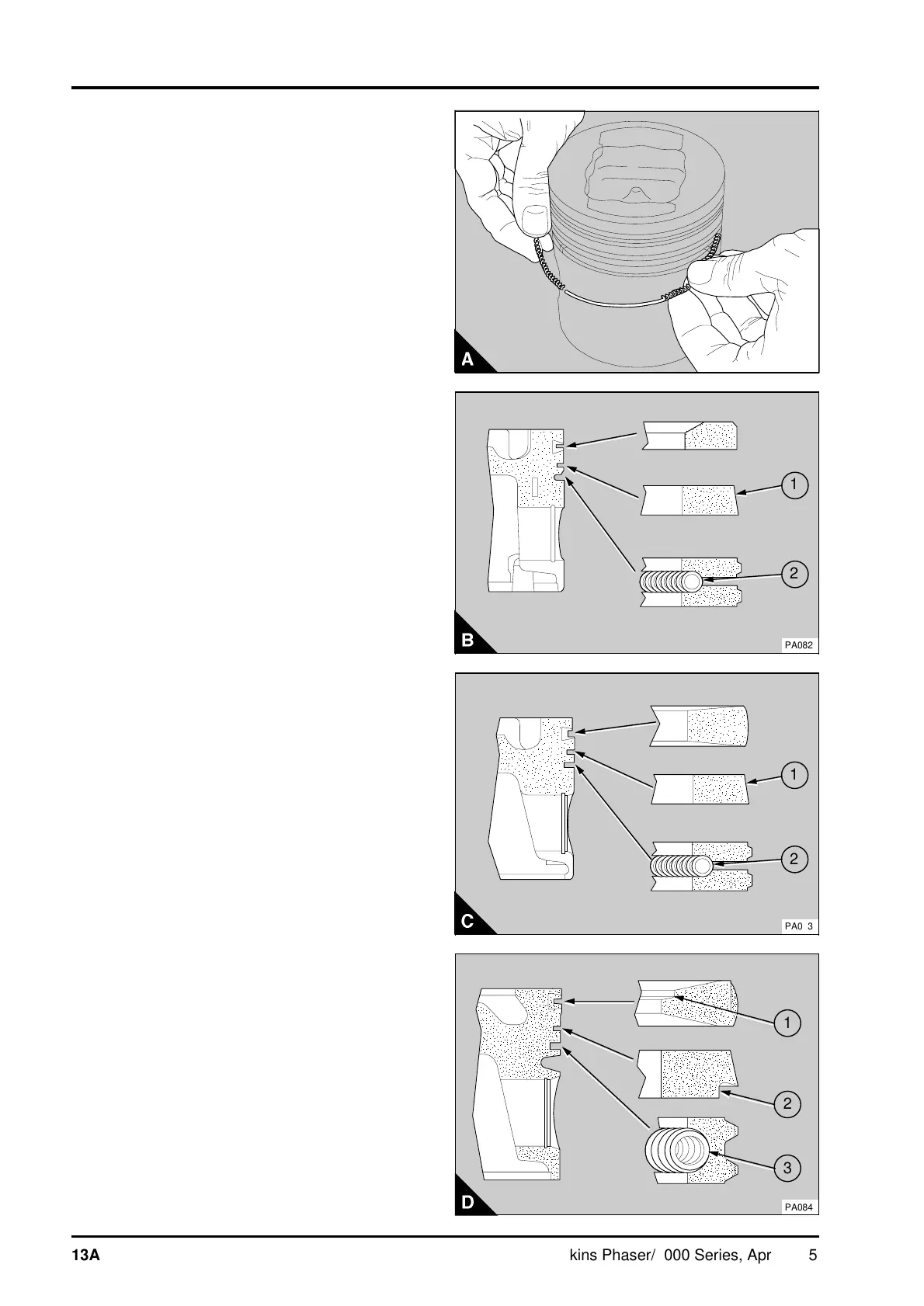
1 Fit the spring of the oil control ring in the bottom
groove with the latch pin inside both ends of the
spring (A). Fit the oil control ring over the spring
(B2, C2 or D3). Ensure that the ring gap is at 180°
to the latch pin.
2 Fit the cast iron ring with the taper face
(B1 or C1) to the second groove with the word
"TOP", or the manufacturer's symbol, towards the
top of the piston.
New second rings have a green identification mark
which must be on the left of the ring gap when the
ring is fitted and the piston is upright.
The second ring on some engines has an outside
step (D2) at the bottom of the tapered face.
3 Fit the chromium plated top ring, the
manufacturer's symbol or the word 'TOP' must be
towards the top of the piston.
New top rings have a red or blue identification mark
which must be on the left of the ring gap when the
ring is fitted and the piston is upright.
The top ring on some engines has an internal step
(D1) on the top face.
4 Ensure that the ring gaps are 120° apart.
PA081
a
a
1
a
a
2
PA082
a
a
1
a
a
a
2
PA083
13A.10 Perkins Phaser/1000 Series, April 1995