14 CRANKSHAFT ASSEMBLY
Caution: Do not use a degreasing solution.
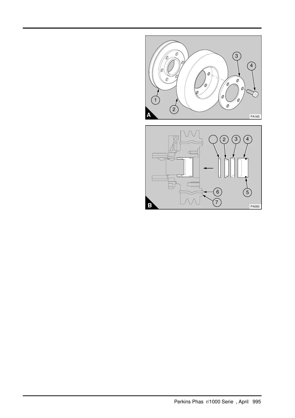
2 Clean thoroughly the nose of the crankshaft, the
bore of the pulley and the tapered rings
components. Do not expand the tapered rings.
3 Put the pulley on the crankshaft with the key
engaged and push the pulley towards the rear.
4 Fit the spacer (B1), then the inner ring (B2) and
then the outer ring (B3). Ensure that the ring gaps
are not aligned.
Caution: It can be very difficult to remove the
pulley if the tapered rings are not fitted correctly.
5 Lubricate lightly the "O" ring (B5) and the
threads and the thrust faces of the setscrews with
clean engine oil. Put the thrust block (B4) and
setscrews in position.
6 While the pulley is pressed to the rear, tighten
the setscrews gradually and evenly to 115 Nm
(85 lbf ft) 11,8 kgf m. Apply the torque again to
ensure the pulley is fully tightened.
7Fit the drive belts, operation 23A-04.
a
a
3
4
PA165
a
a
1
a
a
2
4
3
a
a
2
1
5
a
a
6
PA093
7
14A.06 Perkins Phaser/1000 Series, April 1995