CRANKSHAFT ASSEMBLY 14
Rear oil seal assembly - engines which
have a flywheel housing that is oil filled
To remove and to fit14A-02B
Special tools:
Replacer tool for rear oil seal, PD.145D
Consumable products:
POWERPART Threadlock
POWERPART Silicone rubber sealant
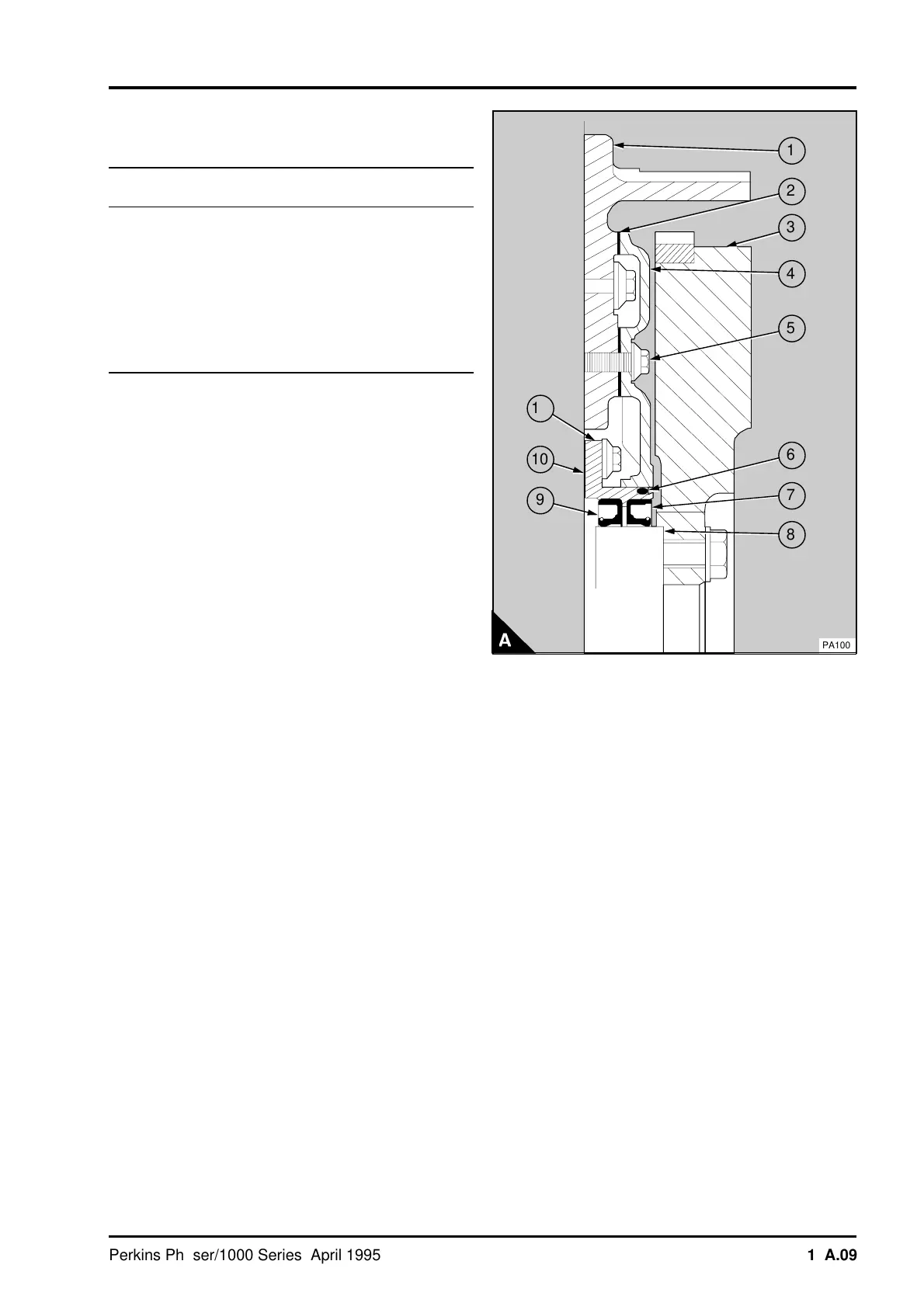
This arrangement for the crankshaft rear oil seal is
for engines which have a flywheel housing that is
filled with oil. This arrangement uses two lip seals
which are narrower than the standard seal and are
fitted back to back on the crankshaft palm. The
front seal (A9) prevents leakage of oil from the
engine and the rear seal (A7) prevents leakage of
oil from the flywheel housing. A cover (A4) and joint
(A2) are used to prevent leakage of oil past the
setscrews which retain the flywheel housing (A1) to
the rear face of the cylinder block. An "O" ring (A6)
is used to seal between the cover and the seal
housing. Oil leakage past the "O" ring or one of the
oil seals will pass through a hole in the seal housing
between the two seals. The oil will then pass
through two cast grooves in the front face of the
flywheel housing. These grooves are in the
4 o'clock and 8 o'clock positions.
To remove
1 Release the setscrews which retain the flywheel
and remove the flywheel (A3).
2 Release the setscrews (A5) which retain the
cover (A4) and remove the cover. On later covers
their are two integral lugs to enable the use of a
lever to remove the cover. Remove the joint (A2)
and clean the joint faces of the cover and flywheel
housing.
3 Release the setscrews and the cap screws and
washers which retain the housing (A11) for the rear
oil seals and remove the housing. Clean the joint
faces of the seal housing and cylinder block.
a
a
1
a
a
a
2
a
a
a
3
a
a
4
a
a
a
5
a
a
6
a
a
a
7
a
a
8
a
a
9
a
a
a
a
a
a
10
a
a
a
a
11
PA100
Perkins Phaser/1000 Series, April 1995 14A.09