Watchdog 258 May 03, 2004
Philips Semiconductors Preliminary User Manual
LPC2119/2129/2194/2292/2294ARM-based Microcontroller
Watchdog Mode Register (WDMOD - 0xE0000000)
The WDMOD register controls the operation of the Watchdog as per the combination of WDEN and RESET bits.
WDEN WDRESET
0 X Debug/Operate without the Watchdog running
1 0 Debug with the Watchdog interrupt but no WDRESET
1 1 Operate with the Watchdog interrupt and WDRESET
Once the WDEN and/or WDRESET bits are set they can not be cleared by software. Both flags are cleared by an external reset
or a Watchdog timer underflow.
WDTOF The Watchdog time-out flag is set when the Watchdog times out. This flag is cleared by software.
WDINT The Watchdog interrupt flag is set when the Watchdog times out. This flag is cleared when any reset occurs.
Watchdog Timer Constant Register (WDTC - 0xE0000004)
The WDTC register determines the time-out value. Every time a feed sequence occurs the WDTC content is reloaded in to the
Watchdog timer. It’s a 32-bit register with 8 LSB set to 1 on reset. Writing values below 0xFF will cause 0xFF to be loaded to the
WDTC. Thus the minimum time-out interval is t
pclk
x 256 x 4.
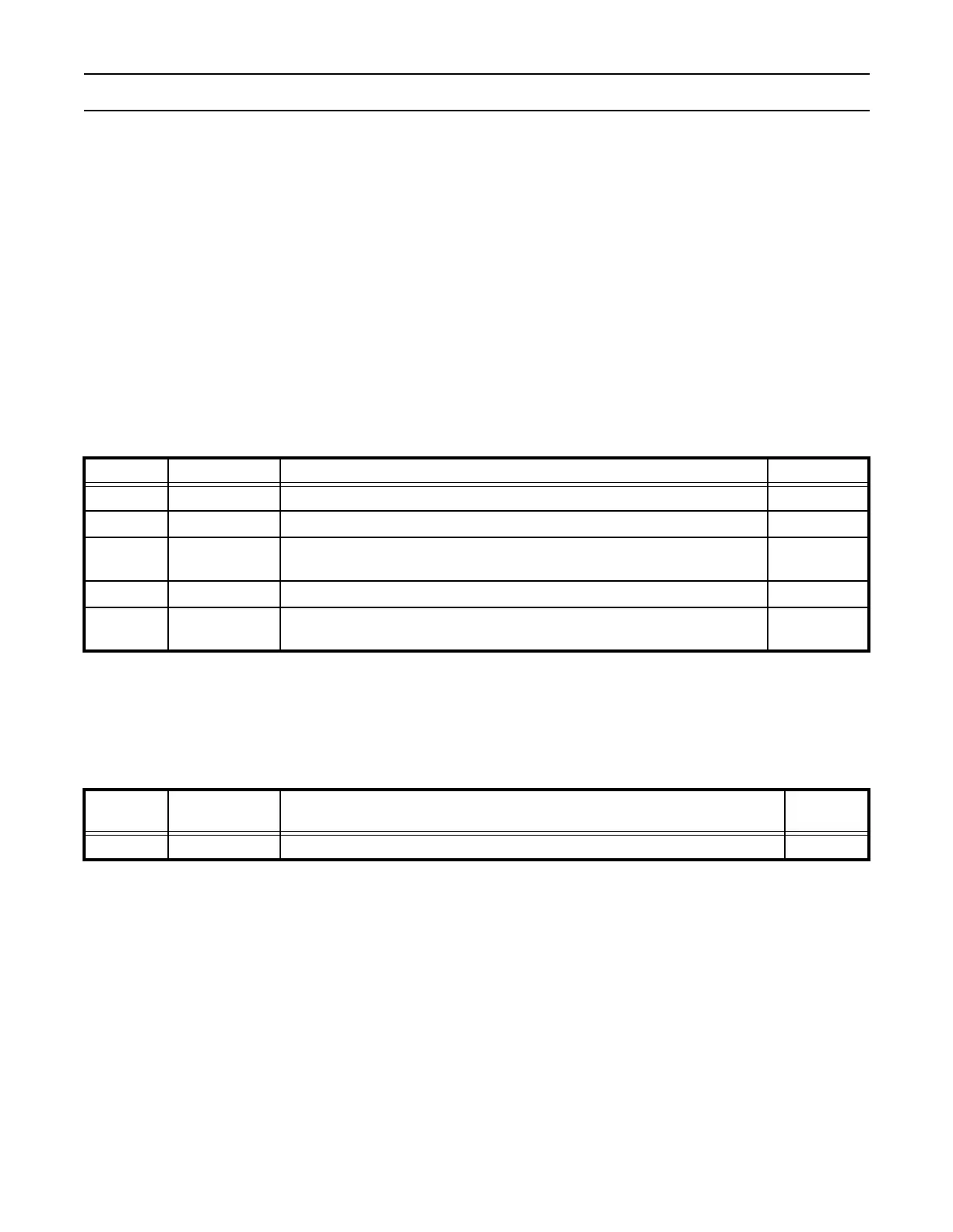
Table 194: Watchdog Mode Register (WDMOD - 0xE0000000)
WDMOD Function Description Reset Value
0 WDEN Watchdog interrupt enable bit (Set only) 0
1 WDRESET Watchdog reset enable bit (Set Only) 0
2 WDTOF Watchdog time-out flag
0 (Only after
external reset)
3 WDINT Watchdog interrupt flag (Read Only) 0
7:4 Reserved
Reserved, user software should not write ones to reserved bits. The value read
from a reserved bit is not defined.
NA
WDTC Function Description
Reset
Value
31:0 Count Watchdog time-out interval 0xFF