7 General
Installation manual for PMC tendo DD5/PMCprimo Drive3 Page 21
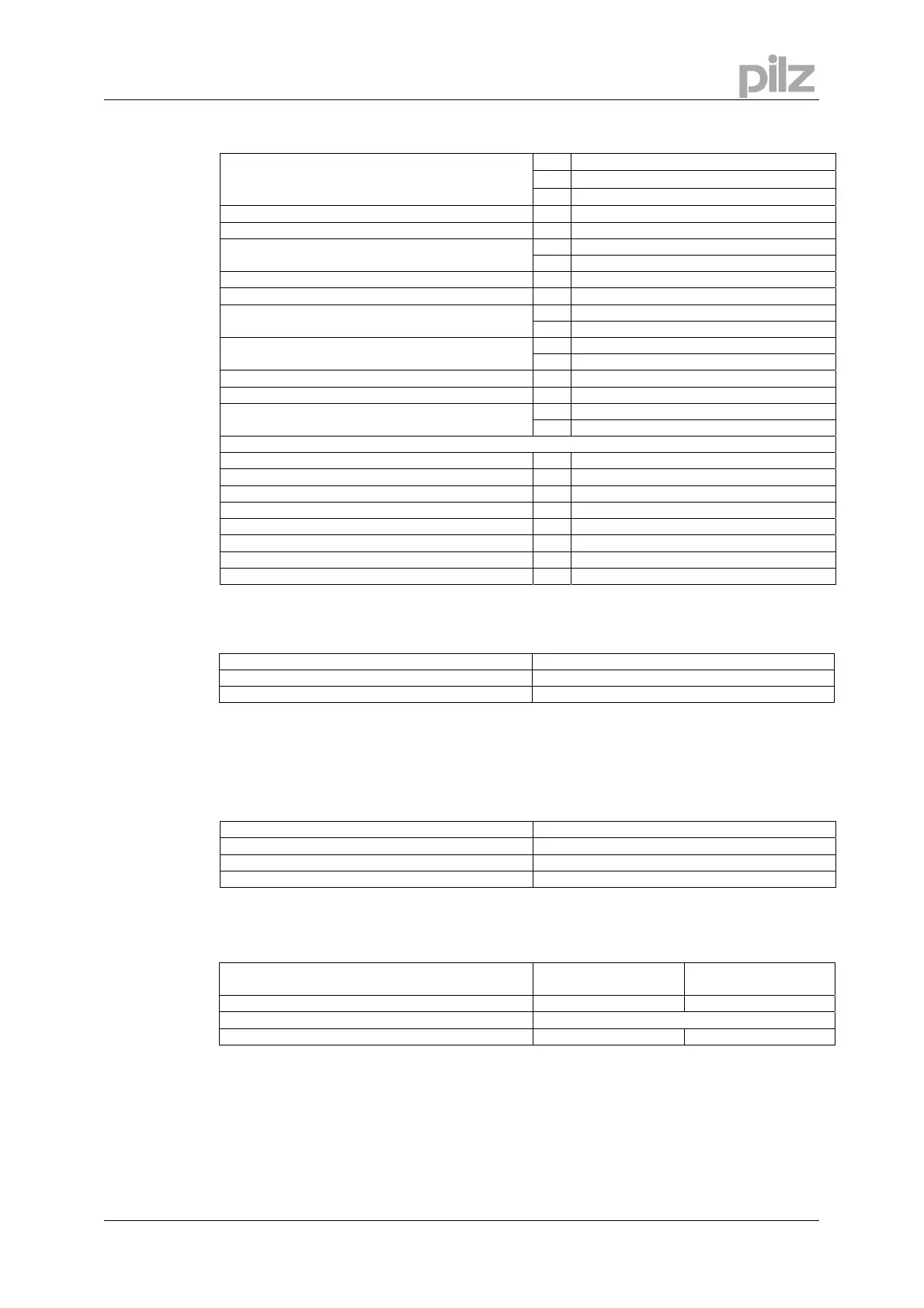
7.7.3 Inputs / outputs
V
±10
V
±10
Analog inputs 1, 2 (resolution 14/12 bit)
Max. common-mode voltage
Input resistance to AGND
kΩ
20
Digital control inputs V as per EN 61131-2 Type 1, max. 30VDC
Digital control outputs, active high V open Emitter, max. 30VDC, 10mA
V DC max. 30, AC max 42
BTB/RTO output, relay contacts
mA 500
Digital inputs (X10) V as per EN 61131-2 Type 2, max. 30VDC
Digital outputs (X10) V open Emitter, max. 30VDC, 100mA
V 20 – 30 Auxiliary supply voltage, electrically isolated,
without brake/fan
A 1.3
V 24 (-0% +15%) Auxiliary supply voltage, electrically isolated, with
brake/fan (check voltage drop !)
A 2.8
Max. output current to brake A 1.5
Master encoder supply V 5-24V, see datasheet encoder
V 12
12V supply CAN
mA 10 each PMCprimo client
Connection technology
Control signals — Combicon connector
Power signals — Combicon connector
Resolver input — SubD 9pol. (socket)
Incremental encoder input — SubD15pol. (socket)
PC- interface, CAN (X6, X11/2) — SubD 9pol. (plug)
CAN (X11/1), Master encoder, CAN-2 (option) — SubD 9pol. (socket)
Encoder emulation, ROD/SSI — SubD 9pol. (plug)
Modbus/Ethernet RJ45 (socket)
7.7.4 Recommended tightening torques
Connector Tightening torque
X0, X8, X9 0.5 .. 0.6 Nm
Grounding bolt 3.5 Nm
7.7.5 Fusing
7.7.5.1 Internal fusing
Circuit Internal fuse
Auxiliary voltage 24V (X4) 3.15 A (slow)
Auxiliary voltage 24V (X10) electronic
Regen resistor electronic
7.7.5.2 External fusing
Wire fuses or similar
1.5A, 3A
6A, 10A
AC supply feed F
N1/2/3
(X0/1; 2; 3) 6 AT (FRx-6) 10 AT (FRx-10)
24V feed F
H1/2
Max. 8 AF (FRx-12)
Regen resistor F
B1/2
(X8/2; 4) 6 AT (FRS-6) 6 AT (FRS-6)
x = S or S-R for 480V applications x = N or N-R for 230V applications
 Loading...