9 Interfaces
Page 78 Installation manual for PMCtendo DD5/PMCprimo Drive3
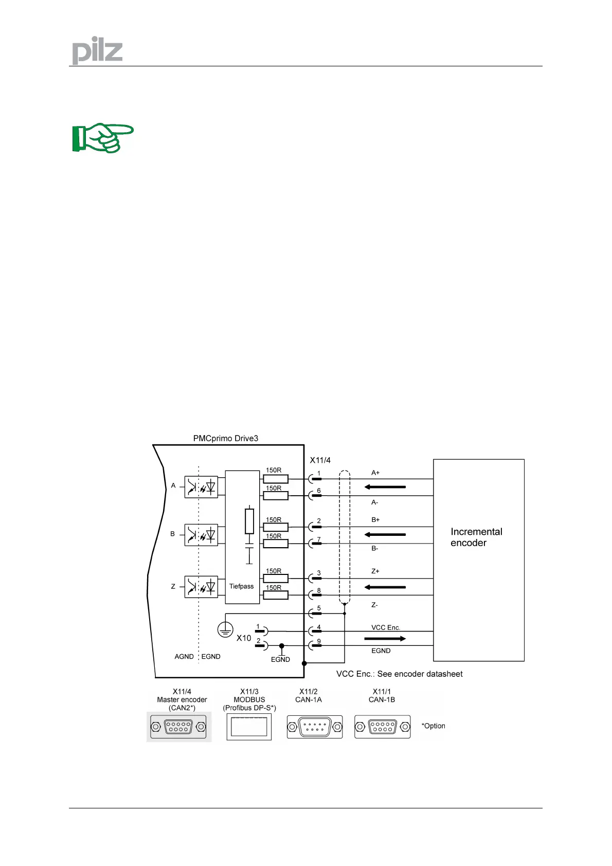
9.15 Master encoder interface (X11/4)
These interface is available only at a PMCprimo Drive3!
The PMCprimo Drive3 is designed for use with incremental or SSI encoders. The encoder type
can easily be changed with the FS command.
With SSI encoders the number of data bits can be set with NB.
The direction of each encoder input can be changed with the command CW. Setting the
direction bit reverses the direction of the encoder without wiring.
If a reference signal occurs, the actual encoder position is stored (see reference inputs page
60). This is useful for product referencing.
For further details see PMCprimo programming manual.
The master encoder is supplied via terminal X10 (pins 1 and 2). See page 45.
9.15.1 Incremental encoder (ROD)
• Reference ground is EGND (terminal X10 Pin 2)
• For encoders with differential line drivers – track A, B and Z (0-Index)
• Quadrature encoder x1, x2 and x4
• Maximum input frequency: 1 MHz
• Minimum track width Z-track: 200 ns
• Maximum voltage range (tracks) ref. to EGND: 5 V DC
 Loading...