Home
Pilz
Industrial Equipment
PMC Series
Pilz PMC Series User Manual
5
of 1
of 1 rating
120 pages
Give review
Manual
Specs
To Next Page
To Next Page
To Previous Page
To Previous Page
Loading...
9 Interfaces
Installation manual for PMC tendo DD5/PM
Cprimo Drive3
Page 45
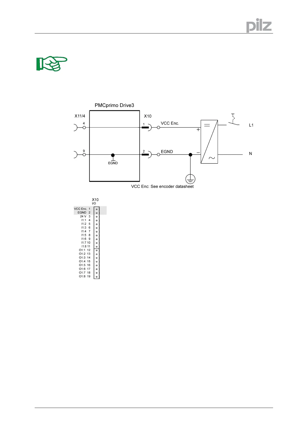
9.3.4
Master encoder supply (X10)
These connectors are available
only at a PMCprimo Drive3!
•
Individual power supp
ly for the connected encoder
•
Voltage range: See encoder datashe
et!
•
External fusing provided by the user
44
46
Table of Contents
1 General Conditions
2
Copyright
2
Notes
2
Previous Editions
2
2 Table of Contents
3
3 Type Key
6
Type Pmctendo DD5
6
Type Pmcprimo Drive3
6
4 Safety Instructions
7
5 European Directives and Standards
8
6 Abbreviations and Symbols
10
7 General
11
About this Manual
11
Requirements
11
Use as Directed
11
Instrument Description
13
Package Supplied
13
Common Accessories
13
Accessories for Pmcprimo Drive3
13
The Pmctendo DD5 Family of Digital Servo Amplifiers
14
The Pmcprimo Drive3 Family of Digital Servo Amplifiers
16
Connection to Various Electrical Supply Networks
17
Components of a Servo System
18
Technical Data
19
Technical Data 230 V Series
19
Technical Data 480 V Series
20
Inputs / Outputs
21
Recommended Tightening Torques
21
Fusing
21
Permissible Ambient Temperatures, Ventilation, Mounting Position
22
Conductor Cross-Sections
22
LED Display
23
Control Circuit for Motor-Holding Brake
24
Grounding System
25
Regen Circuit
25
Functional Description
25
Technical Data
26
Switch-On and Switch-Off Behavior
27
Stop Function as Per en 60204 (VDE 0113)
27
Emergency Stop Strategies
28
8 Installation
29
Guide to Installation and Wiring
30
Assembly
31
Dimensions
32
Wiring
33
Connection Diagram General
34
Connection Diagram Pmcprimo Drive3
35
Connector Assignments General
36
Connector Assignments Pmcprimo Drive3
37
Notes on Connection Technology
38
9 Interfaces
40
Block Diagram General
40
Block Diagram Pmcprimo Drive3
41
Electrical Supply
42
Mains Electrical Supply Connection (X0)
42
Auxiliary Supply (X4)
43
Supply (X10)
44
Master Encoder Supply (X10)
45
DC Bus Link (X8)
46
Motor Connection with Brake (X9)
47
External Regen Restistor (X8)
48
Feedback
49
Resolver X2
49
Comcoder (X1)
50
Incremental or Sine Encoder with Hall Sensors (X1)
51
Sine Encoder with Endat or HIPERFACE (X1)
52
Acuro Encoder, BISS Interface (X1)
53
Incremental Encoder (X5)
54
Sine Encoder Without Data Channel (X1)
55
Digital and Analog Inputs and Outputs
56
Analog Inputs (X3)
56
Digital Inputs (X3/X4)
58
Digital Inputs I1:1 - I1:8 (X10)
60
Digital Outputs (X3)
61
Digital Outputs (X10)
63
Encoder Emulation
64
Incremental Encoder Output - a Quad B (X5)
64
SSI Output (X5)
65
Master-Slave Operation, Encoder Master Control
66
Connection to a Pmctendo DD5 Master, 5V Signal Level (X5)
66
Connection to Incremental Encoder Master with 24V Signal Level (X3)
67
Connection to a Sine Encoder Master (X1)
68
Interface for Stepper Motor Controllers (Step and Direction)
69
Speed Profile and Signal Diagram
69
Connection to a Stepper Controller with 5V Signal Level (X5)
70
Connection to a Stepper Controller with 24V Signal Level (X3)
71
RS232 Interface, PC Connection (X6)
72
Interface Cable between the PC and Servo Amplifier
72
Canopen Interface (X6)
73
CAN-Bus Cable
73
CAN Bus Interface (X11/1,X11/2)
75
General
75
Connecting Pmcprimo Drive3 Systems
75
Speciality 1St Node
76
Speciality Last Node
76
Fault Detection
76
Connecting External Canopen Bus Devices
76
CAN Bus Interface (X11/4)
77
Master Encoder Interface (X11/4)
78
Incremental Encoder (ROD)
78
Absolute Encoder (SSI)
79
Panel Interface - Modbus (X11/3)
80
General
80
Interface
80
Profibus DP Slave Interface (X11/3)
81
General
81
Using the Profibus Interface with Pmcprimo
81
Example Using Profibus DP
82
Ethernet Interface (X11/5)
83
General
83
Interface
83
Configuration IP Address
83
Compact Flash Interface (X11/5)
84
General
84
Interface
84
Personnel Safe Restart Lock -AS
85
Technical Data and Pinning
85
Environment
85
Wiring
85
Functional Description
86
10 Setup
90
Important Notes
90
Guide to Setup
91
Setup Software Pdrive
92
Use as Directed
92
Software Description
92
Hardware Requirements
92
Minimum Requirements for the PC
92
Installation under WINDOWS 2000 / XP
92
Working with Pdrive
93
Parametrization of the Pmctendo DD5 and Pmcprimo Drive3
93
Multi-Axis Systems
93
Keypad Operation Pmctendo DD5
94
Keypad Operation Pmcprimo Drive3
96
Basic Key Operation
96
LED Display
96
Programming of the Pmcprimo Drive3
97
Error Messages Pmctendo DD5
98
Warning Messages Pmctendo DD5
99
Error Messages Pmcprimo Drive3
100
Status Messages Pmcprimo Drive3
101
11 Expansions and Accessories
102
Expansion Cards
102
Guide to Installation of Expansion Cards
102
Expansion Card -I/O-14/08
103
Expansion Card -PROFIBUS
106
Expansion Module -CAN Adapter
107
Pmcprimo Board and Pmcprimo Expansion Card
109
12 Appendix
112
Transport, Storage, Maintenance, Disposal
112
Finding and Removing Faults
113
Glossary
116
Index
118
5
Based on 1 rating
Ask a question
Give review
Questions and Answers:
Need help?
Do you have a question about the Pilz PMC Series and is the answer not in the manual?
Ask a question
Pilz PMC Series Specifications
General
Brand
Pilz
Model
PMC Series
Category
Industrial Equipment
Language
English
Related product manuals
Pilz PNOZ
8 pages
Pilz PSS 4000
43 pages
Pilz PSEN sl-0.5p 1.1
35 pages