10 Setup
Page 98 Installation manual for PMCtendo DD5/PMCprimo Drive3
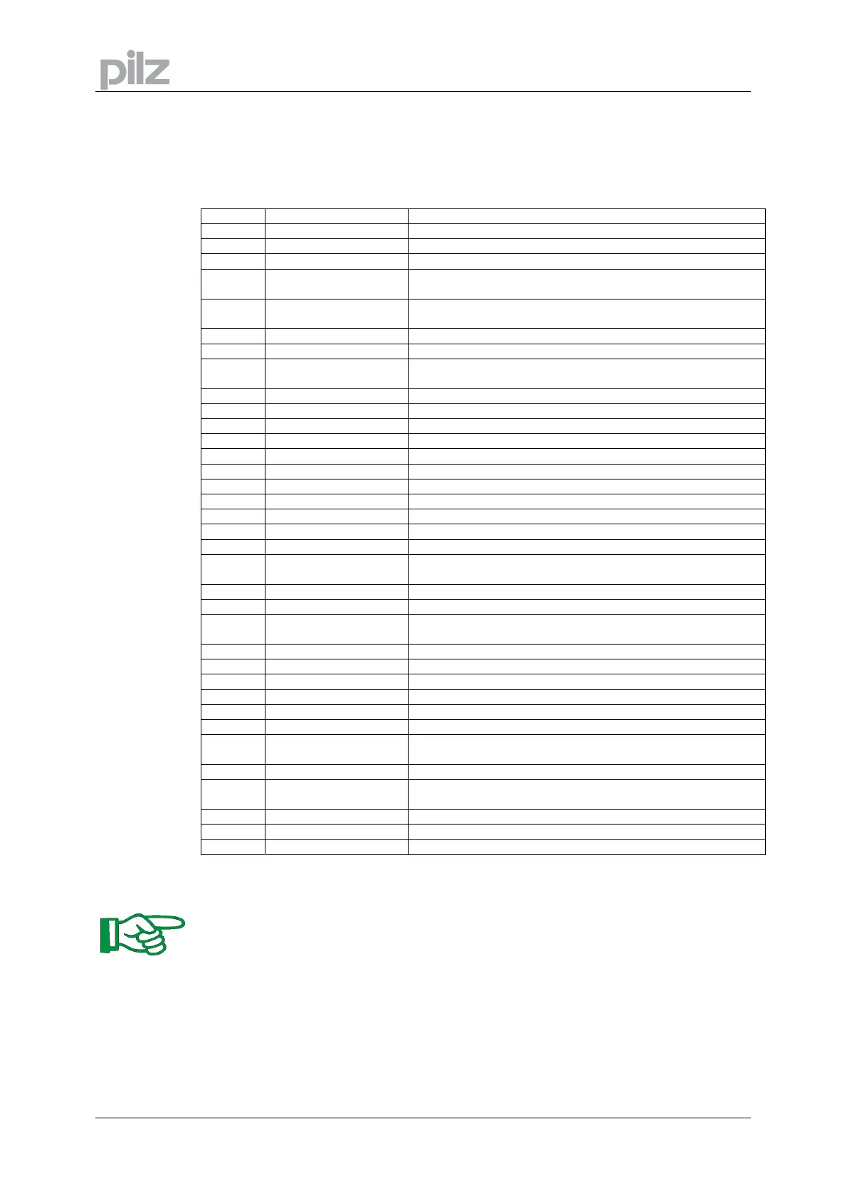
10.6 Error messages PMCtendo DD5
Any errors that occur are shown in coded form by an error number in the LED display on the
front panel. All error messages result in the BTB/RTO contact being opened, and the output
stage of the amplifier being switched off (motor loses all torque), and the motor-holding brake is
activated. Detailled description see "ASCII command reference".
Number Designation Explanation
E/S/A/P
status Messages status messages, no error, see p. 94
. . .
status Message amplifier is updating the startup configuration
-
status Message status message, no error, programming mode
F01*
heat sink temperature heat sink temperature too highlimit is set by manufacturer to
80°
F02*
overvoltage overvoltage in DC bus linklimit depends on the electrical
supply voltage
F03*
following error message from the position controller
F04
feedback cable break, short-circuit, short to ground
F05*
undervoltage undervoltage in DC bus linklimit is set by manufacturer to
100V
F06
motor temperature motor temperature too high or temp. sensor defect
F07
reserved reserved
F08*
overspeed motor runs away, speed is too high
F09
EEPROM checksum error
F10
signal failure X5 signal failure X5 (cable break or similar)
F11
brake cable break, short-circuit, short to ground
F12
motor phase motor phase missing (cable break or similar)
F13*
ambient temperature ambient temperature too high
F14
output stage fault in the power output stage
F15
I²t max. I²t maximum value exceeded
F16*
mains BTB/RTO 2 or 3 phases missing in the mains supply feed
F17
A/D converter error in the analog-digital conversion, normally caused by
extreme electromagnetic interference
F18
regen regen circuit faulty or incorrect setting
F19*
DC bus link DC bus link breakdown
F20
slot error slot error, depends on the type of expansion card (see ASCII
command reference)
F21
handling error Handling error on the expansion card
F22
reserved reserved
F23
CAN-bus off severe CAN bus communication error
F24
warning warning is displayed as fault
F25
commutation error commutation error
F26
limit switch hardware limit switch error on homing move
F27
AS operational error with -AS- , input for AS-Enable and
ENABLE have been set at the same time
F28
fieldbus error fieldbus error (see ASCII command reference)
F29
fieldbus error fieldbus communication is disturbed (see ASCII command
reference)
F30
emergency timeout Timeout emergency stop
F31
reserve reserve
F32
system error system software not responding correctly
* = these error messages can be cleared without a reset, by using the ASCII command
CLRFAULT. If only one of these errors is present and the RESET button or the I/O RESET
function is used, only the CLRFAULT command will be executed.
You can find further information on handling errors from page 113 and in the "ASCII
command reference" (part of the setup software's online help system)
 Loading...