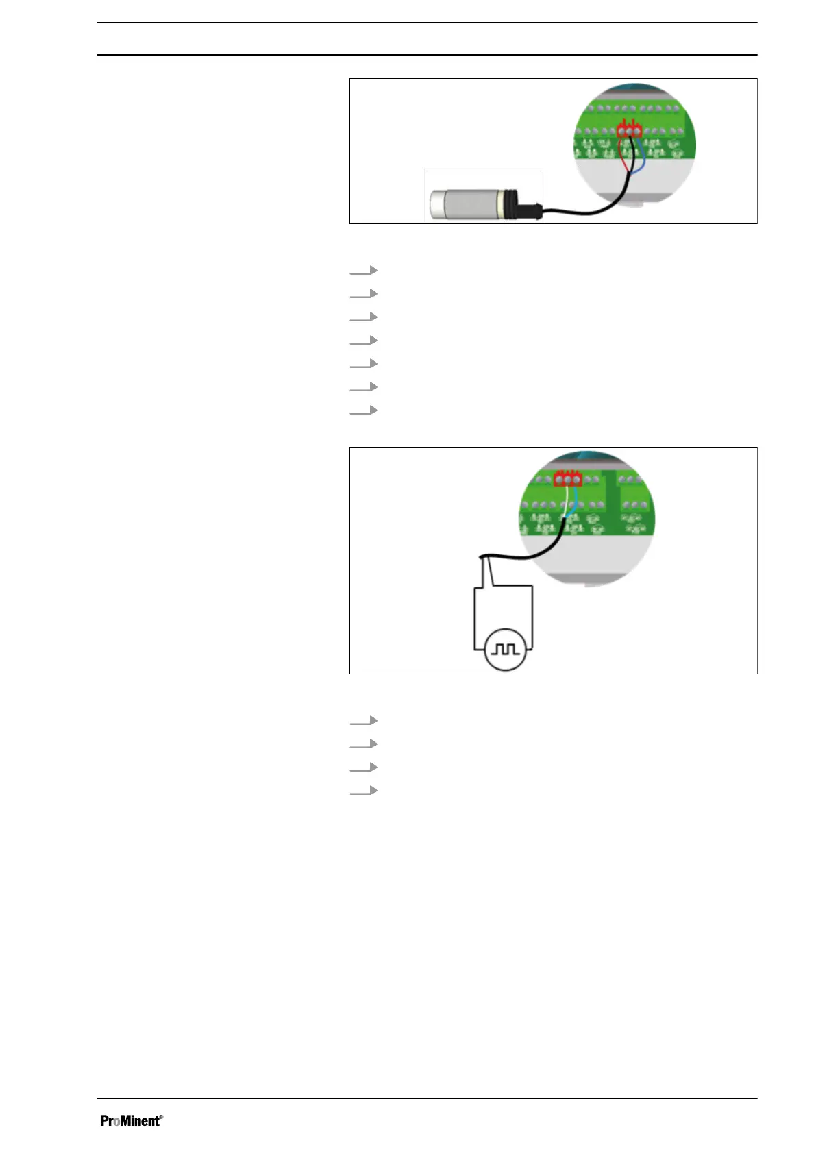
Fig. 15: Connection of a flow switch sensor to DI2
1. Remove the protective sleeve of the cable.
2. Strip away 7 mm of the insulation on the leads.
3. Guide the cable through the cable gland.
4. Connect the brown lead to DI2 (Plus) (33).
5. Connect the blue power lead to DI2 (minus) (35).
6. Connect the black lead to DI2 (SW) (34).
7. Tighten the cable gland to form a seal.
Fig. 16: Connection of a flow meter sensor to DI3
1. Use a two-lead cable.
2. Connect a sensor lead to connector DI3 (SW) (23).
3. Connect the other sensor lead to connector DI3 (minus) (24).
4. Tighten the cable gland to form a seal.
Connection of a flow switch sensor to
DI2:
Connection of a flow meter sensor to
DI3:
Installation and assembly
25