8. Tighten the cable gland to form a seal.
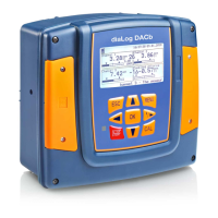
The controller has 4 digital inputs to which a tank floor, a flow or
another sensor or an R.I.C. (Remote Input Control) can be con‐
nected.
Fig. 13: Digital inputs DI1 ... DI4
Tab. 8: The supported sensors are defined as follows:
0 ... 20 l/min 0 ... 50 l/min 0 ... 200 l/min 0 ... 10 m3/H Customer*
Flow rate
(pulses)
-• -• -• -•
(*): The customer’s scale can be defined between 0 ... 2000 (l/min, l/h or m
3
/h) in 4...20 mA or pulse input.
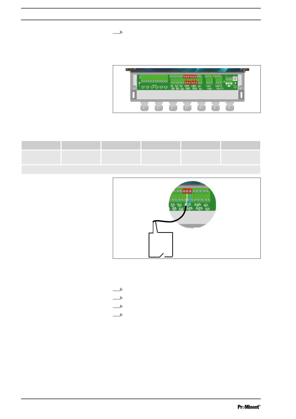
Fig. 14: Connection of a tank floor, a flow or another sensor or an
R.I.C. (Remote Input Control)
1 Contact
1. Use a two-lead cable.
2. Connect a sensor lead to connector DI1 (SW) (20).
3. Connect the other sensor lead to connector DI1 (minus) (21).
4. Tighten the cable gland to form a seal.
Digital inputs DI1 ... DI4
Connection of a tank floor, a flow or
another sensor or an R.I.C. (Remote
Input Control)
Installation and assembly
24