Tab. 5: The supported sensors are defined as follows:
-5 … +45 °C Customer*
Temperature -• -•
(*): The customer’s scale can be defined between -10 ... 100 °C.
Tab. 6: The supported sensors are defined as follows:
0 ... 5
mS/cm
0 ... 10
mS/cm
0 ... 20
mS/cm
0 ... 50
mS/cm
0 ... 100
mS/cm
0 ... 200
mS/cm
Customer*
Conduc‐
tivity
-• -• -• -• -• -• -•
(*): The customer’s scale can be defined between 0 ... 2000 (µS/cm, mS/cm).
Tab. 7: The supported sensors are defined as follows:
Customer*
Volume (4 ... 20 mA) -•
(*): The customer’s scale can be defined between 0 and 2000 (litres, m
3
).
0 ... 20 l/min 0 ... 50 l/min 0 ... 200 l/min 0 ... 10 m3/H Customer*
Flow rate
(4 ... 20mA)
-• -• -• -•
(*): The customer’s scale can be defined between 0 ... 2000 (litres/min, litres/h or m
3
/h) in 4...20mA or
pulse input.
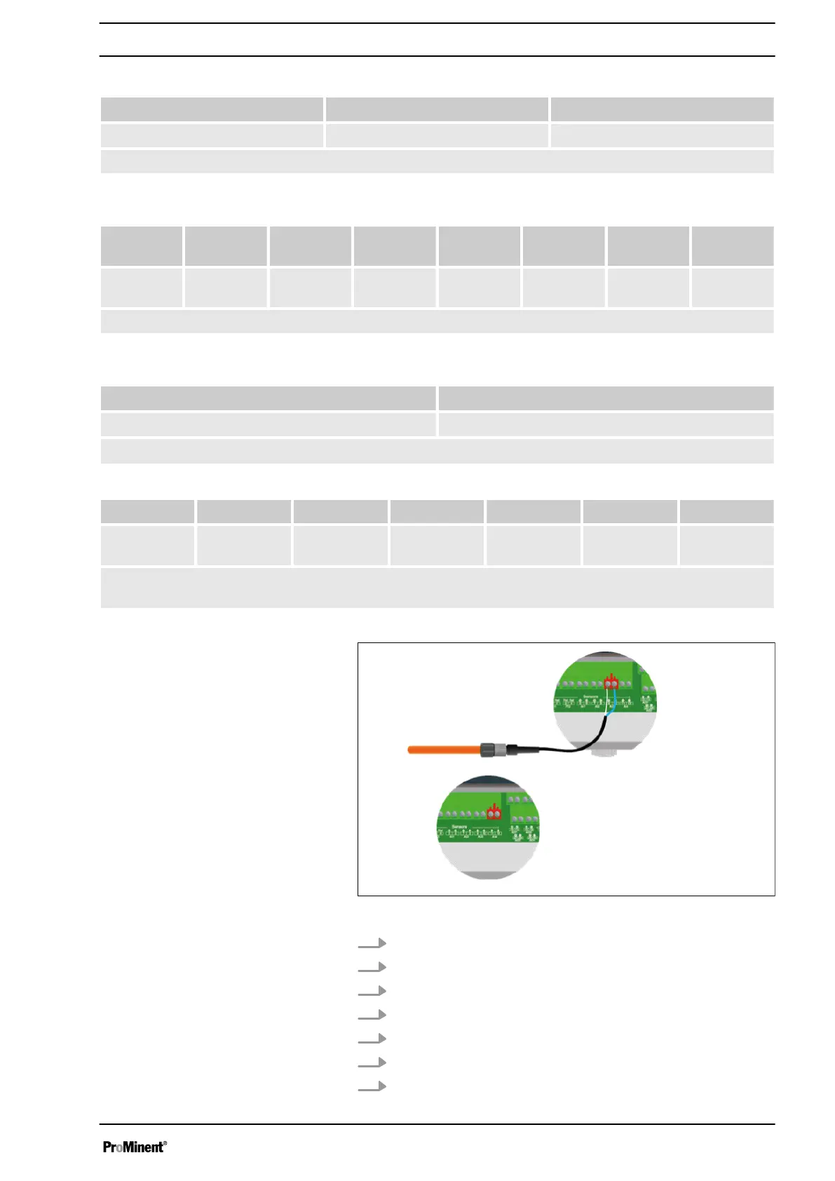
Fig. 12: Connecting the sensors AI3 and AI4
1. Use a two-lead cable.
2. Connect the sensor (+) lead to the connector AI3 + (9).
3. Connect the sensor (-) lead to the connector AI3 - (10).
4. Tighten the cable gland to form a seal.
5. Use a two-lead cable.
6. Connect the sensor (+) lead to the connector AI4 + (11).
7. Connect the sensor (-) lead to the connector AI4 - (12).
Connecting the sensors
Connecting the sensor to AI3:
Connecting the sensor to AI2:
Installation and assembly
23