0.01...
0.5
mg/l
0.1...1
mg/l
0.02...
2 mg/l
0.1...5
mg/l
0.2...1
0 mg/l
0.4...1
5 mg/l
0.2...2
0 mg/l
0.5...5
0 mg/l
1...10
0 mg/l
2...20
0 mg/l
20...2
000
mg/l
Cus‐
tomer
*
Free
bro‐
mine
-• -• -• -•
Per‐
acetic
acid
-• -• -•
Ozon
e
-• -•
Dis‐
solved
oxyge
n
-• -• -•
PHMB -• -•
* The customer’s scale can be defined between 0 ... 2000 (ppb, ppm, NTU, µg/l, mg/l, g/l or %)
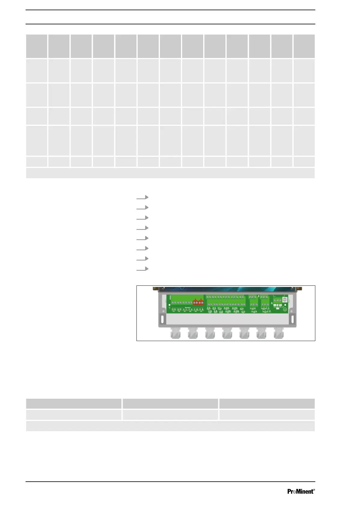
1. Use a two-lead cable.
2. Connect the sensor (+) lead to the connector AI1 + (5).
3. Connect the sensor (-) lead to the connector AI1 - (6).
4. Tighten the cable gland to form a seal.
5. Use a two-lead cable.
6. Connect the sensor (+) lead to the connector AI1 + (7).
7. Connect the sensor (-) lead to the connector AI1 - (8).
8. Tighten the cable gland to form a seal.
Fig. 11: A3001
The device has two analogue inputs 4 ... 20 mA, which are not
insulated and to which an insulated temperature, conductivity, tur‐
bulence, flow or volume sensor can be connected.
Tab. 4: The supported sensors are defined as follows:
0.2 ... 100 NTU Customer*
Turbidity -• -•
(*): The customer’s scale can be defined between 0 ... 2000 (NTU or FNU).
Connecting the sensors
Connecting the sensor to AI1:
Connecting the sensor to AI2:
Analogue inputs 4...20 mA uninsu‐
lated AI3 & AI4
Installation and assembly
22