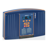
The self-fed PO1 and PO2 relays have a TR5 fuse. If a fuse is
destroyed, a special symbol (see figure opposite) appears on the
relevant output.
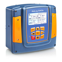
A bar diagram (1) showing the metering capacity of the 4 ... 20 mA
output. Of 0 ... 100%.
Rotation (2) according to the capacity.
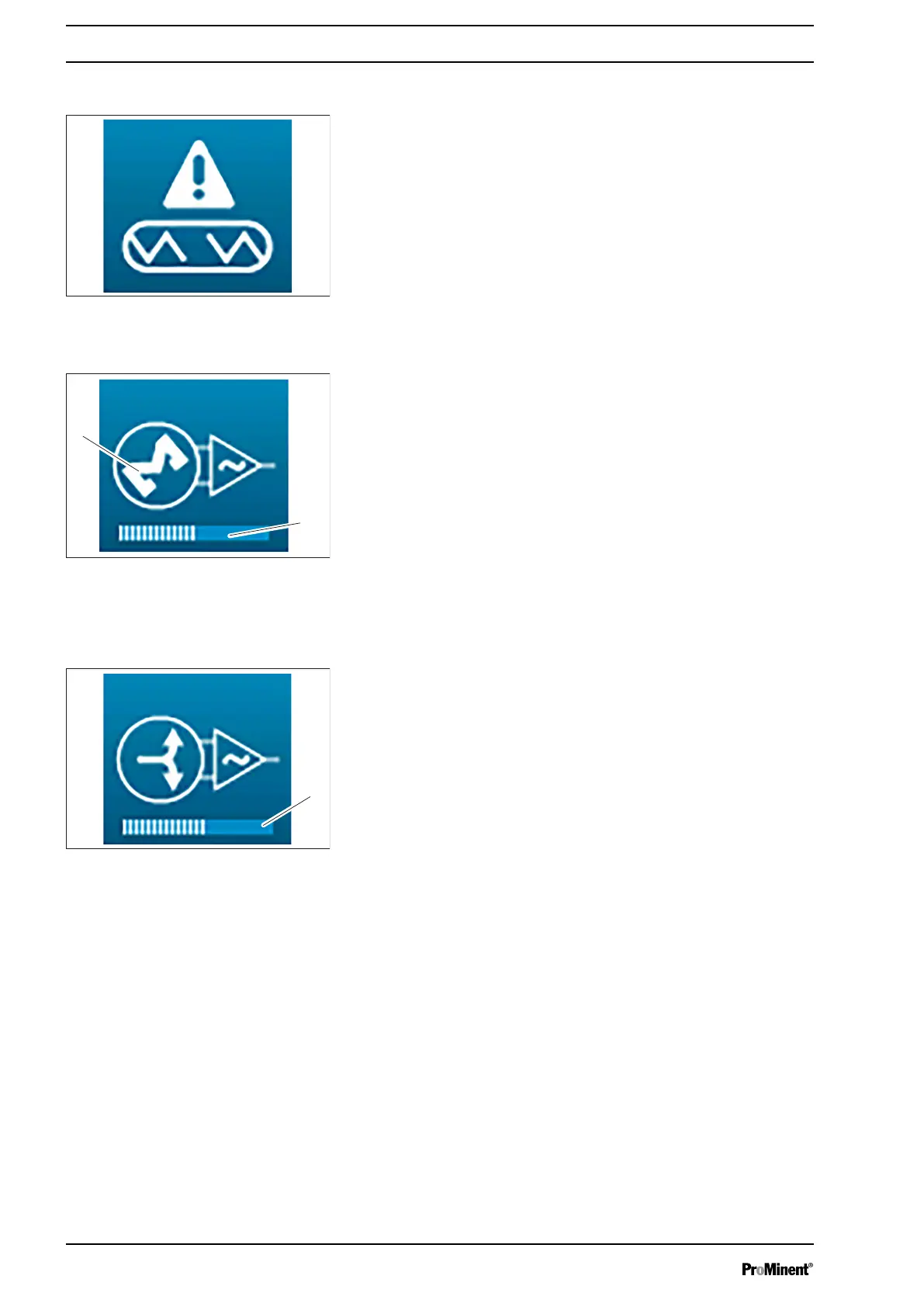
A bar diagram (1) showing the level of the 4...20 mA output. From
0/4 mA ... 20 mA.
Protective fuse out of action
Fig. 34: Protective fuse out of action
4 ... 20mA output in metering mode
Fig. 35: 4 ... 20mA output in metering
mode
4 ... 20mA output in transmission
mode
Fig. 36: 4 ... 20mA output in transmis‐
sion mode
Operating concept and operation
34