PLX51-PBM Operation
PROFIBUS DPV0/DPV1 Master or Slave to EtherNet/IP™ or Modbus® Gateway User Manual
ProSoft Technology, Inc. Page 115 of 196
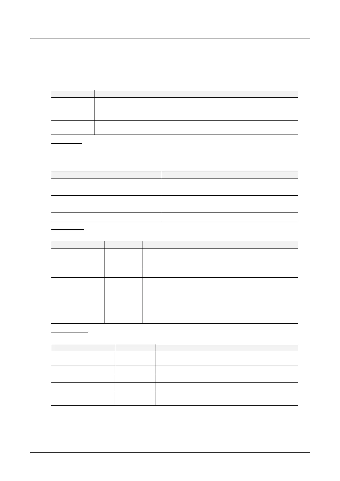
Extraction
The user can extract diagnostics by using the slave device node address. The user
can also decide how the diagnostics data must be extracted. This is changed by
updating the mode in the Diagnostics Request message. There are one of three
modes that can be selected:
Table 5.25 – Diagnostics Extract Message
Read the slave device diagnostics that has been buffered in the PLX51-PBM.
Read the slave device diagnostics that has been buffered in the PLX51-PBM and clear
the Diagnostics Pending indication.
Force the PLX51-PBM to send a PROFIBUS Diagnostic Request to the specific slave
device and return the diagnostics data received.
CIP Message
Below are the EtherNet/IP CIP message parameters as well as the request and
response data structures.
Table 5.26 – Diagnostics Extract Message
Request Data:
Table 5.27 – Diagnostics Extract Request
The amount of time (in milliseconds) the PLX51-PBM waits for a
DPV1 response before timing out and responding to the
EtherNet/IP request with a Timeout Status.
The station number of the PROFIBUS device.
0 – Read the slave device diagnostics that has been buffered in
the PLX51-PBM.
1 – Read the slave device diagnostics that has been buffered in
the PLX51-PBM and clear the Diagnostics Pending indication.
2 – Force the PLX51-PBM to send a PROFIBUS Diagnostic
Request to the specific slave device and return the diagnostics
data received.
Response Data:
Table 5.28 – Diagnostics Extract Response
This is the status of the DPV1 data exchange. See
appendix for the definitions of the returned status.
The number of diagnostic bytes that have been returned.
Refer to the PROFIBUS Specification EN 50170 for
information regarding the diagnostics.
 Loading...

