EasyManuals Logo

Pulsar ULTRA TWIN User Manual

Pulsar ULTRA TWIN
225 pages
To Next Page IconTo Next Page
To Previous Page IconTo Previous Page
Page #26 background imageLoading...
Page #26 background image
Page 18
Transducer
The transducer should be installed, and connected, in accordance with the
installation instructions contained in the Transducer User Guide.
The entire range of, standard dB transducers are certified for use in
hazardous areas and different models, for each, are available for use in Zone
1 or Zone 0.
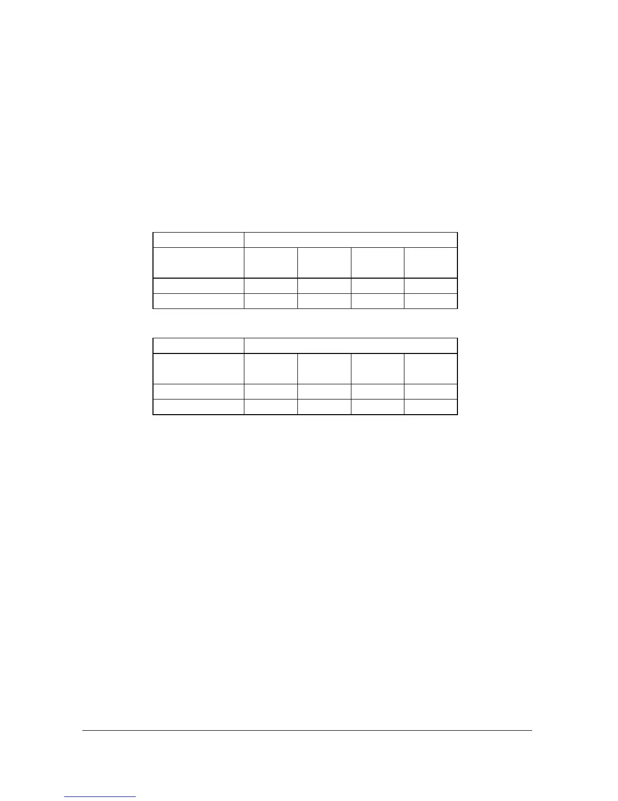
Wire the transducer to the Ultra Twin’s transducer terminals, terminal
numbers will depend on the unit type, as follows:
Transducer 1
Terminal Connection Details
Unit Type
Red
Power
White
Signal
Black
0 volts
Green
Screen
Wall Mount
45
46
47
47
Fascia Mount
32
31
30
30
Transducer 2
Terminal Connection Details
Unit Type
Red
Power
White
Signal
Black
0 volts
Green
Screen
Wall Mount
48
49
50
50
Fascia Mount
35
34
33
33
If splicing, it is recommended using a junction box with standard twisted,
shielded pair at 20 AWG.
When using 2-core screened extension cable, the Black and Green wires of
the transducer should be connected to the screen of the extension cable,
which in turn should be connected to the relevant 0 volts terminal.

Table of Contents

Other manuals for Pulsar ULTRA TWIN

Questions and Answers:

Question and Answer IconNeed help?

Do you have a question about the Pulsar ULTRA TWIN and is the answer not in the manual?

Pulsar ULTRA TWIN Specifications

General IconGeneral
BrandPulsar
ModelULTRA TWIN
CategoryMeasuring Instruments
LanguageEnglish

Related product manuals