Page 22
Fuse Location
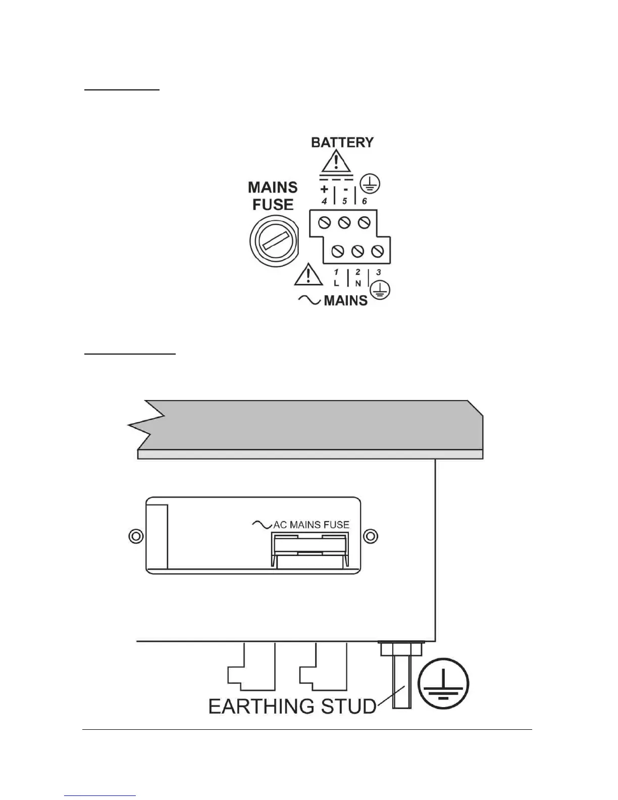
Wall mount
The mains fuse is located, inside the terminal compartment, to the left of
the mains terminals, as illustrated below.
Fascia mount
The mains fuse is located under the removable cover at the bottom of the
unit, as illustrated below.

 Loading...


