Page 140
P*305 Input Filter
This parameter is used to ignore spurious changes of state on the digital
inputs and determines the time that a change of state has to be present before
it is recognised as a valid input.
Enter the required filter time in seconds. Default = 1 second.
Digital Inputs
P1 and P2
The Twin provides 4 Digital Inputs on the Wallmount model and seven on
the Facsia model.
The following parameters are used to configure the use of the digital inputs.
P*372, P*375, P*378, P*381, P*384, P*387, P*390 - Type
Determines the way digital inputs will be recognised by the Ultra Twin.
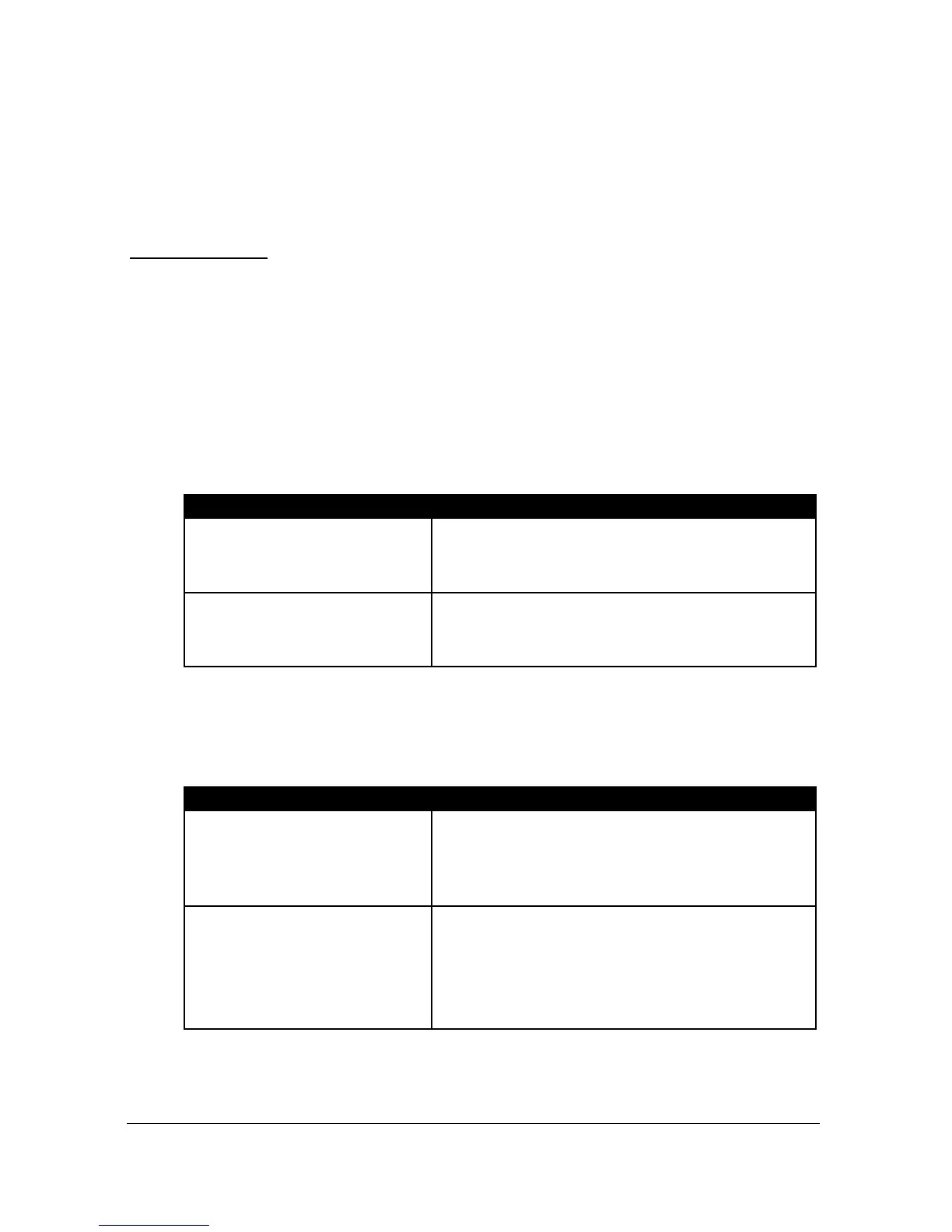
Ultra Twin recognises a closed condition,
D.C. signal voltage present at the input,
as a healthy/run condition.
Ultra Twin recognises an open condition,
D.C. signal voltage not present at the
input, as a healthy/run condition.
P*373, P*376, P*379, P*382, P*385, P*388, P*391 - Function
This parameter will set the function of the digital Input.
Digital input is used to Fail, (put out of
service), a device connected to the relay
specified in P*374, 377, 380, 383, 386,
389, 392 Assignment.
Digital input is used to select the device,
(pump), connected to the relay specified in
P*374, 377, 380, 383, 386, 389, 392
Assignment as the current duty device
(pump).

 Loading...


