119
1) Slave address and CRC code: See “Table A.2”.
2) Command code: 06H. Request to write 1 word (2 bytes) of the slave.
3) Communication address: The address of read data. This is not the real physical
address for data storage, but a number corresponding to the data. Every control,
state or monitoring parameter of QD200 series frequency inverter corresponds to
a communication address. See “A2.5 Communication parameter”.
4) Write data: Request data written by the slave.
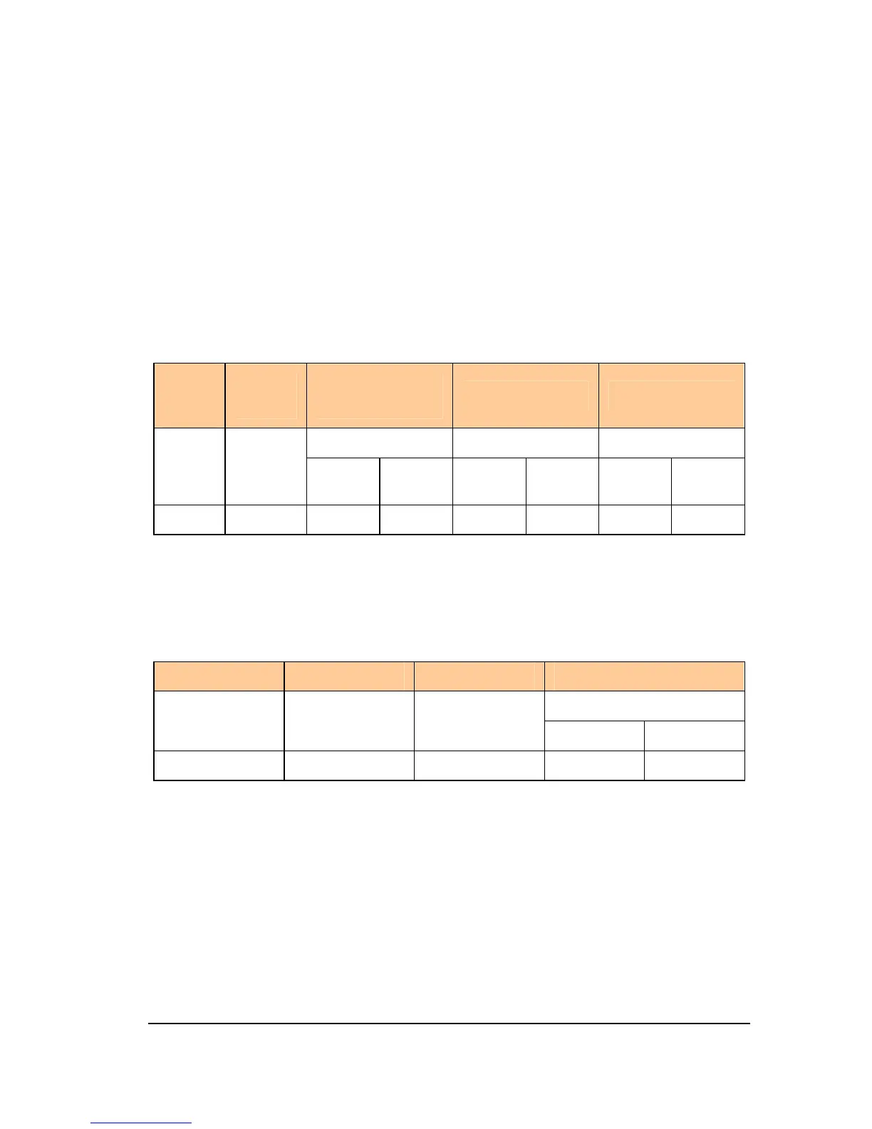
2. Slave normal response message
Table A.7 Slave normal response message
Slave
addres
s
Comma
nd code
1 byte
High
byte
Low
byte
High
byte
Low
byte
Low
byte
High
byte
06H
Slave’s normal response message is the same as the master’s request message.
3. Slave error response message
Table A.8 Format of slave error response message
Slave address
Error code CRC code
2 bytes
1 byte 1 byte 1 byte
Low byte High byte
86H
1) Slave address and CRC code: See “Table A2.2”.
2) Command code: 86H. It is = 06H + 80H.
3) Error code. For detail see “A2.4 Error code”.
4. Example: To write upper limit frequency
Master request message: 01 06 00 08 13 24 05 23 (Suppose that the set upper limit
frequency is 49 Hz)
 Loading...