122
A2.5 Communication parameter
1. Control parameter
Control parameters are edited through serial communication in order to realize inverter’s
function setting, running frequency setting, start/stop control and logic/analog output
setting.
1) Basic parameters
Basic parameters consist of 10 groups: F0 – F9. They are used to control the function
setting of the inverter. Their detailed description, communication addresses and value
ranges are shown in “5. Detailed description of parameters”.
Note: The communication address of the basic parameter corresponds to its display
code. However, it is required to change F at the highest bit to 0;
Another example: The display code of parameter “Default keyboard panel display value”
is f702, so the corresponding communication address is 0702.
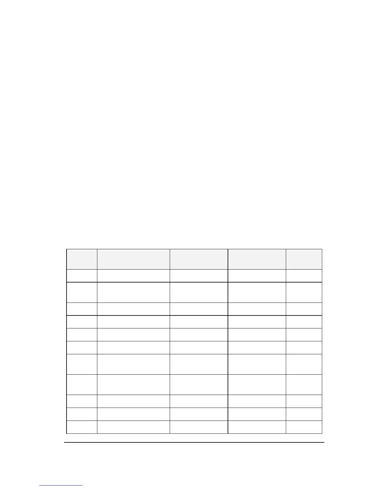
2) Communication control word (Communication address:FA05)
Table A.10 Detailed description of communication control word
Bit
Description of
function
0 1
Default
value
0 JOG NO-JOG Jog frequency 0
1
Forward/reverse
rotation
Forward rotation
0
2 Running/stop Stop Running 0
3 Free stop No action Free stop 0
4 Emergency stop No action Emergency stop
 Loading...