Default
f425 PTC thermal selection 0~2 0
0: Disabled
1: Enabled (trip mode), If the PTC probe triggers the signal of fault, the inverter enters
into fault state and displays “e-25”.
2: Enabled (alarm mode), if the PTC probe triggers the signal of fault, the inverter will
trigger fault signal and continues running.
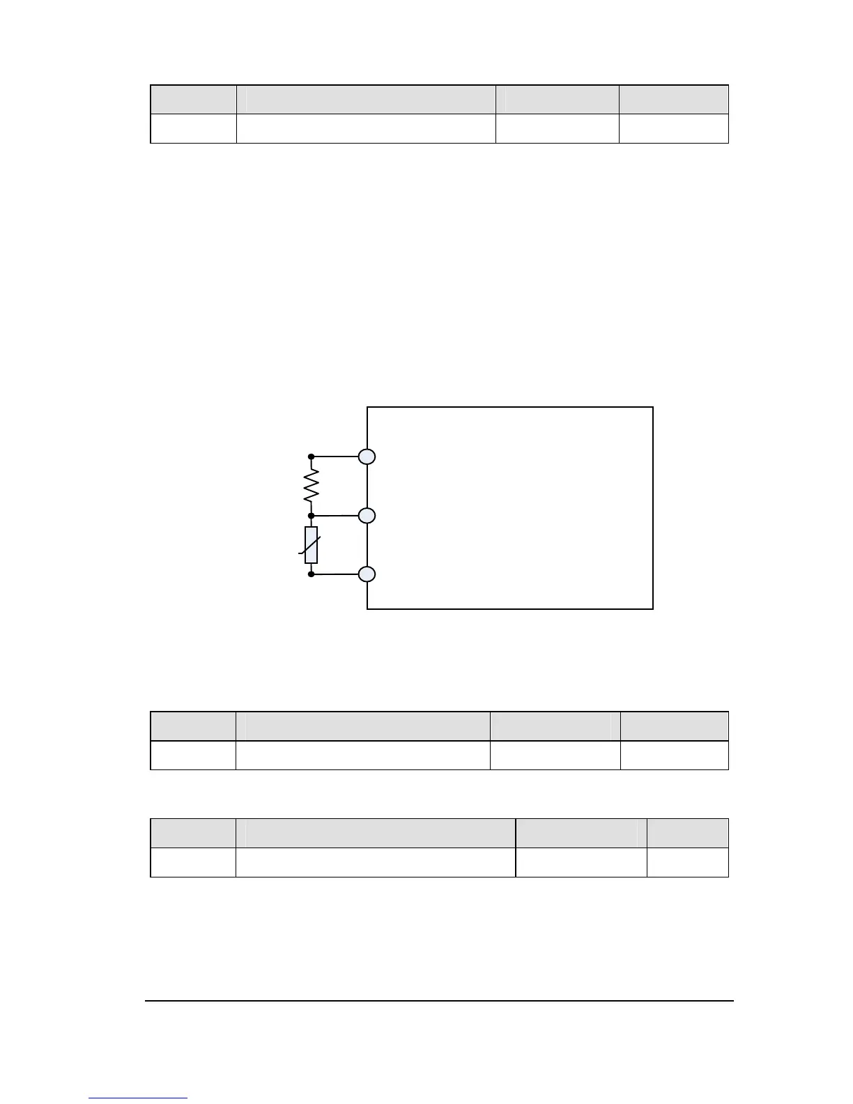
This function is used to protect motor from overheating using the signal of PTC built-in
motor.Setting f425 to 1 or 2 can convert control terminal AI2 to a PTC motor thermal
probe input. The wiring is shown in the following figure.
Figure 2.24 PTC wiring example
Note: PTC resistance must be connected in from AI2 terminal. One 3.3k-1/4 W
resistance must be externally connected between 10 V and AI2.
NO. Parameter Name Setting Range Default
f426 Resistor value for PTC detection 100~9999 Ω 3000
NO. Parameter Name Setting Range Default
f428 Cumulative operation time alarm setting
0.0~999.9 610.0
This parameter allows you to set the inverter so that it will put out an alarm signal
(Output terminal function = 50) after a lapse of the cumulative operation time set with
f428.
Note: 0.1=10h.
10
 Loading...