52
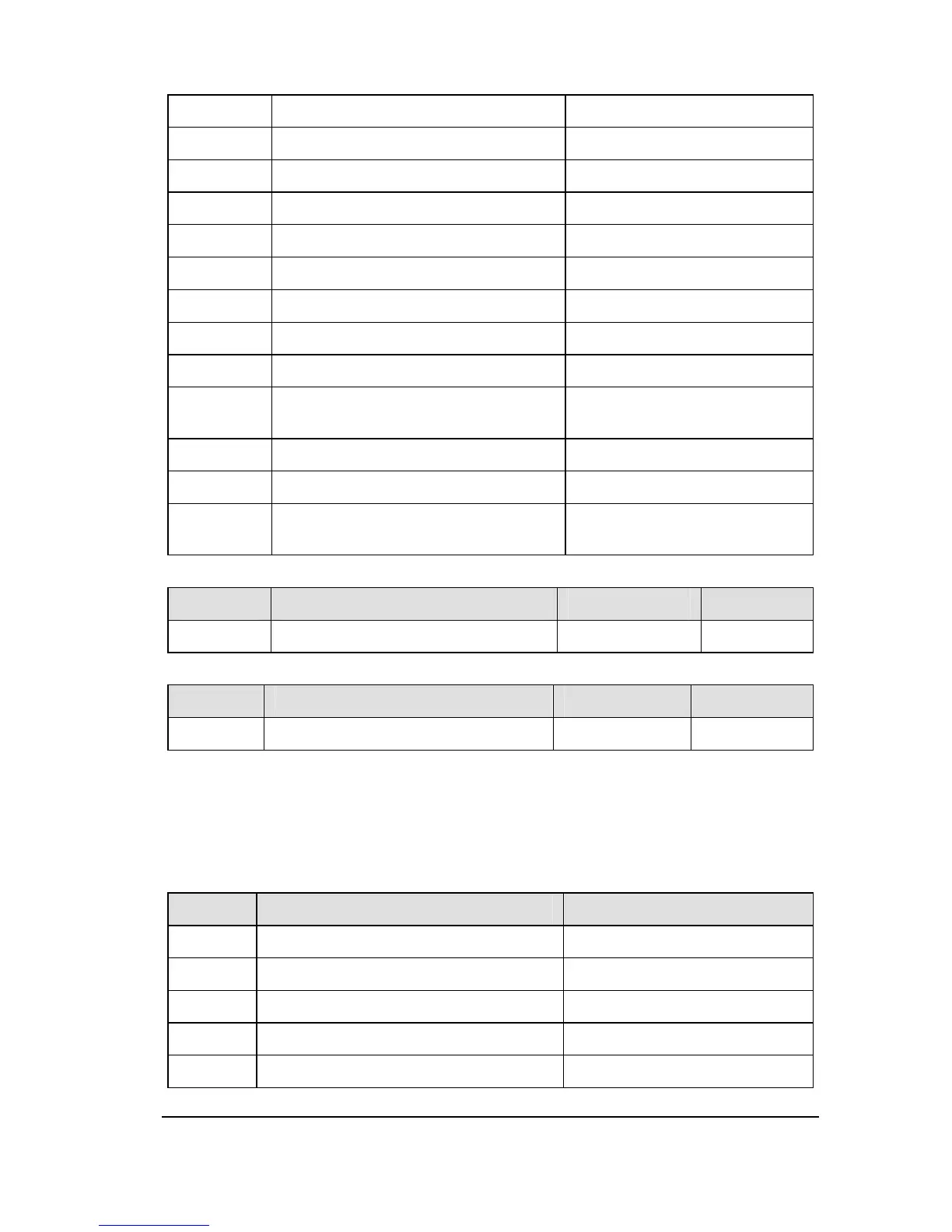
2 Set frequency (Before PID) f007
3 Frequency setting value (After PID)
f007
4 DC voltage
150% of inverter rated voltage
5 Output voltage command value 150% of inverter rated voltage
6 Input power
185% of inverter capacity
7 Output power 185% of inverter capacity
8 AI1 Input value 5V /10V/20mA
9 AI2 Input value 10V
10 Torque 250% of motor rated torque
11 Torque current
250% of motor rated torque
current
12 Motor cumulative load factor 100%
13 Inverter cumulative load factor 100%
14
PBR (braking reactor) cumulative
load factor
100%
NO. Parameter Name Setting Range Default
f347 Maximum numbers of pulse train 500~1600 800
NO. Parameter Name Setting Range
Default
f348 AO1 selection 0~16 0
The signal of internal calculated value can output from the AO1 terminal. Analog voltage
output signal is default. Switching to 0-20mAdc (4-20mAdc) output current can be made
by setting f307 to 0.
Table 2.5 AO selection parameters
f348 description maximum value
0 Output frequency Maximum frequency f007
1 Output current 150% of invter rated current
2 Set frequency (before PID) Maximum frequency f007
3 Frequency setting value (after PID) Maximum frequency f007
4 DC voltage 150% of inverter rated voltage
 Loading...