48
NO. Parameter Name Setting Range Default
f325 AI1 input point 1 setting 0~100% 0
f326 AI1 input point 1 frequency 0.0~400.0 Hz 0.0
f327 AI1 input point 2 setting 0~100% 100
f328 AI1 input point 2 frequency 0.0~400.0 Hz 50.0
f329 AI2 input point 1 setting 0~100% 0
f330 AI2 input point 1 frequency 0.0~400.0 Hz 0.0
f331 AI2 input point 2 setting 0~100% 100
f332 AI2 input point 2 frequency 0.0~400.0 Hz 50.0
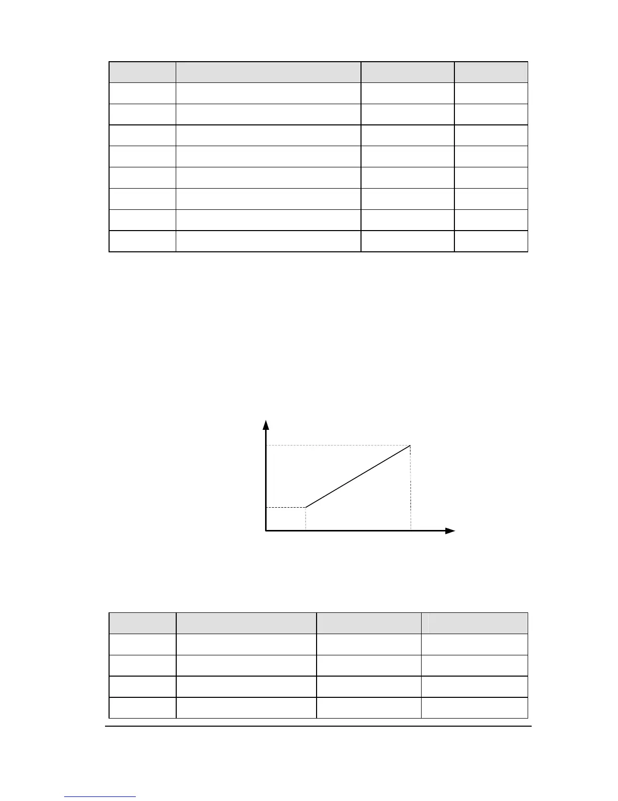
These parameters adjust the output frequency according to the externally applied analog
signal (0-5Vdc voltage, 0-10Vdc voltage, 4-20mAdc current) and the entered command
for setting an external contact frequency, see figure 2.11.
Note 1: Do not set the same value to f325 and f327 (or f329 and f331), otherwise a-05
will alarmed.
Note 2: when adjust 4-20mAdc current input, set 20(%) to f325 (f327).
Note 3: Further adjustment of the analog input signal and bias can be performed using
the parameters f333 and f336.
%
Hz
0
AIx input point 1
frequency
AIx input point 2
frequency
AIx input point 1
setting
AIx input point 2
setting
Figure 2.11 Relation between analog input and frequency setting
NO. Parameter Name Setting Range Default
f333 AI1 input bias 0~255 varies by model
f334 AI1 input gain 0~255 varies by model
f335 AI2 input bias 0~255 varies by model
f336 AI2 input gain 0~255 varies by model
 Loading...