49
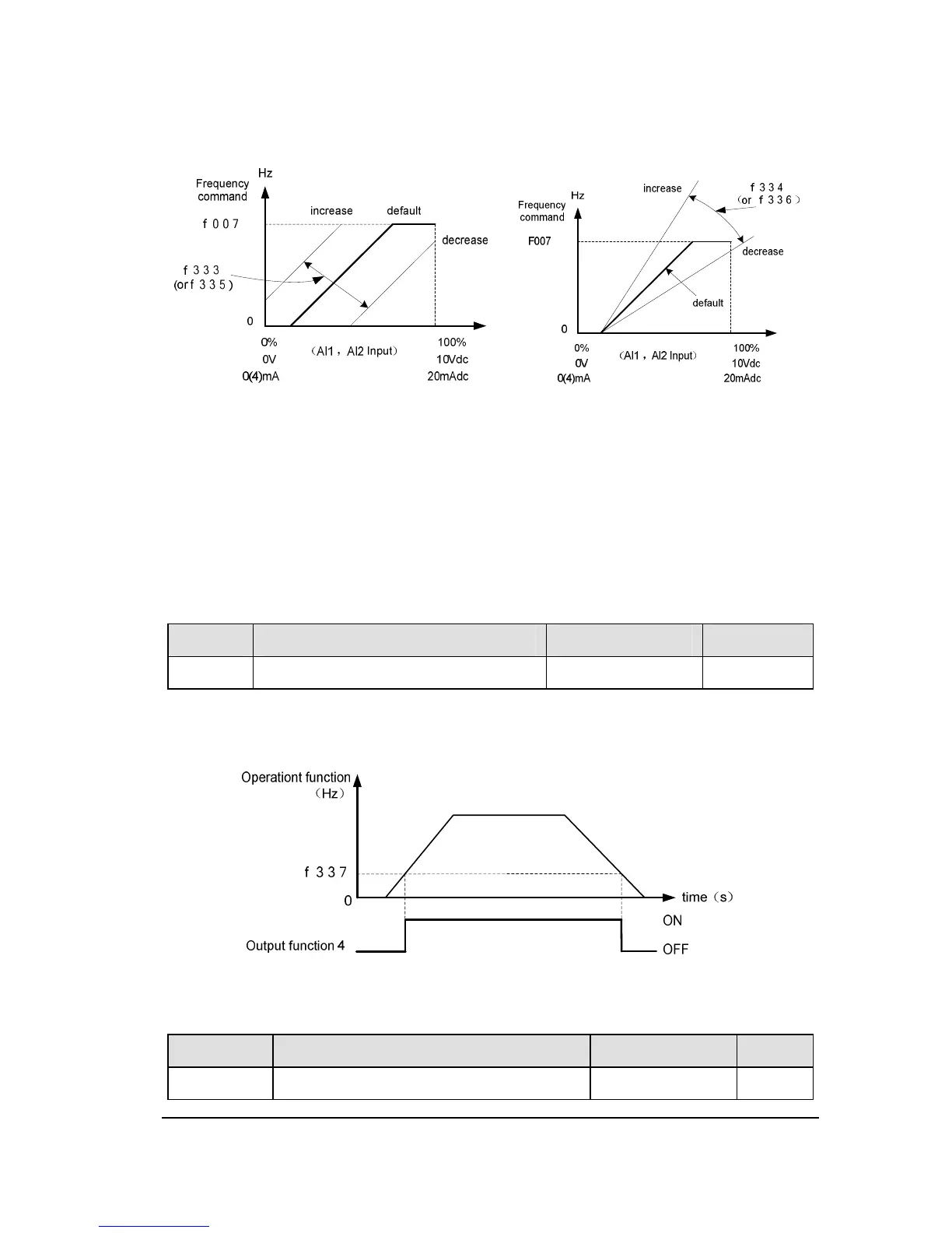
To fine adjust the frequency command characteristics for AI1/AI2 input, use the
Parameters f333 to f336.
Figure 2.12 Calibration of analog input
Note 1: If you want to reach the required signal level before reducing the output
frequency and voltage of inverter. You should increase the input gain. Conversely, you
need to reduce it.
Note 2: If you want to reduce the required signal level when starting motor, you should
increase the input bias, otherwise it needs to reduce. If the input bias is set too high, the
inverter may start the motor at VIA or VIB without a signal.
NO. Parameter Name Setting Range Default
f337 Low-speed signal output frequency
0.0 Hz ~f007 0.0
When the output frequency exceeds the setting of f337, an ON signal will be generated.
This signal can be used as an electromagnetic brake excitation/release signal.
Figure 2.13 Description of Low-speed signal output frequency
NO. Parameter Name Setting Range Default
 Loading...