EasyManua.ls Logo

Qirod QD100 Series User Manual

Default Icon
163 pages
To Next Page IconTo Next Page
To Previous Page IconTo Previous Page
Page #14 background imageLoading...
Page #14 background image
12
f310
Forced- effective Logic input function
selection 2
0
0
f522 Prohibit motor reverse
0 0
Note: When two-wire control is applied, logic input function 30 must be disabled.
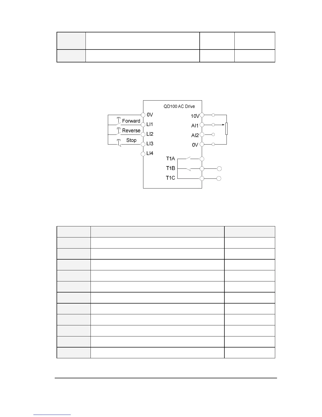
Example 2: Three-wire control running(Negative logic, decelerates to stop)
Figure 1.8 Example of wiring for three-wire control running
Table 1.4 Parameter configuration of 3-wire control running
Code Parameter Set value
f002 Selection of run command 0
f003 Selection of frequency command selection 1
f300 AI1 input function (analog or logic selection) 0
f301 LI1 logic input function 2
f302 LI2 logic input function 3
f303 LI3 logic input function 30
f305 Logic input mode setting 0
f306 Logic input type selection 1
f309 Forced- effective Logic input function selection 1
f310 Forced- effective Logic input function selection 2 0
f522 Prohibit motor reverse 0
Example 3: Three-wire control running(Negative logic, motor stops freely)

Table of Contents

Question and Answer IconNeed help?

Do you have a question about the Qirod QD100 Series and is the answer not in the manual?

Qirod QD100 Series Specifications

General IconGeneral
BrandQirod
ModelQD100 Series
CategoryDC Drives
LanguageEnglish

Summary

BASIC OPERATION AND TRIAL RUNNING

Parameter Setting Mode

Guides users on how to access and change inverter parameters.

Switching on and confirmation of display status

Pre-operation checks and confirmation steps before powering on.

DETAILED PARAMETER DESCRIPTION

Basic parameter group

Covers fundamental parameters for inverter operation.

Motor and its protection parameter group

Parameters related to motor configuration and protection settings.

Motor control parameter group

Parameters for fine-tuning motor control characteristics.

Fault protection parameter group

Parameters related to fault detection and protection functions.

Process PID parameter group

Covers additional PID control parameters and configurations.

FAULT DIAGNOSIS AND MEASURES

Fault code, cause and measures

Lists fault codes, their causes, and troubleshooting steps.

Description of alarm and indication code

Explains various alarm and indication codes displayed by the inverter.

APPENDIX A: SERIAL COMMUNICATION