32
A drop in supply voltage may cause fluctuations of the load current or vibration of the
motor. In some cases, such phenomena can be eliminated by changing the setting of
f210 to between 80 and 90. However, this may cause an increase in load current, so that
it is also necessary to adjust the setting of the electronic thermal protective level 1
parameter (f106) properly according to the motor capacity.
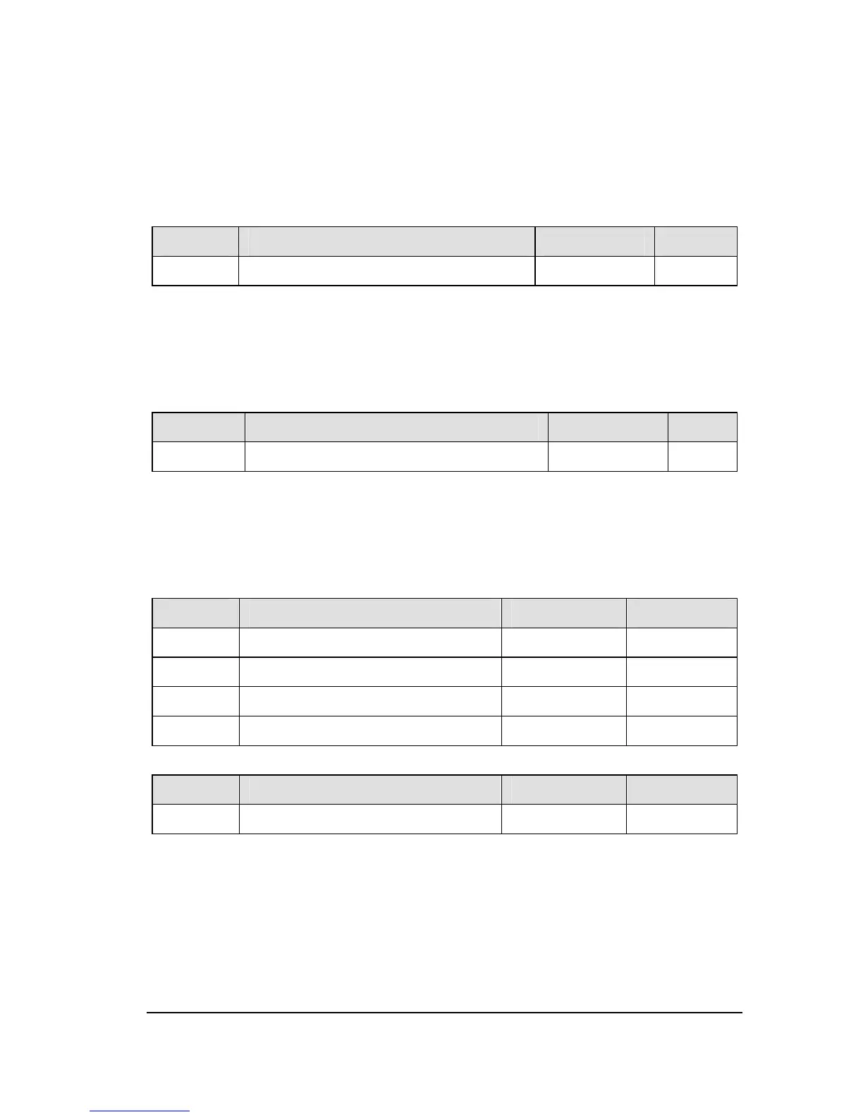
NO. Parameter Name Setting Range
Default
f211 Maximum voltage adjustment coefficient
90~120% 104
Specify a larger value for f211 to secure as high an output voltage as possible in a region
(region where magnetic field is weak) above the base frequency. Setting f211 to a larger
value may cause the motor to vibrate or gears to squeak. If such a phenomenon occurs,
do not adjust this parameter.
NO. Parameter Name Setting Range
f212 Waveform switching adjustment coefficient
0.1~14.0kHz 14.0
Specify a larger value for f212 if switching from a waveform to another resulting in a
considerable increase in vibration and noise in middle-speed range (region between the
start frequency and the base frequency). If no improvement can be made by specifying a
larger value, do not adjust this parameter.
NO. Parameter Name Setting Range
Default
f213 factory reserved
f214 factory reserved
f215 factory reserved
f216 factory reserved
NO. Parameter Name Setting Range
Default
f217 Multi-point profile V/F patter 0~2 0
0: factory reserved.
1: factory reserved.
2: Enable multi-point profile V/F patter. Can set F218~F223 to determine V/f curve.
The drive utilizes a set V/f pattern (f217 = 2) to determine the appropriate output voltage
level for each relative to the frequency reference.
 Loading...