EasyManuals Logo

Qirod QD100 Series User Manual

Default Icon
163 pages
To Next Page IconTo Next Page
To Previous Page IconTo Previous Page
Page #35 background imageLoading...
Page #35 background image
33
NO. Parameter Name Setting Range Default
f218 point 1 output frequency
f1
0~f220 10.0
f219 point 1 output frequency voltage
V1
0~100% 20.0
f220 point 2 output frequency
f2
f218~f220 20.0
f221 point 2 output frequency voltage
V2
0~100% 40.0
f222 point 3 output frequency
f3
f220~f101 30.0
f223 point 3 output frequency voltage
V3
0~100% 60.0
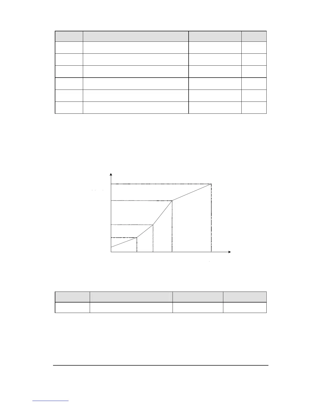
Set up the V/f pattern with f218~f223 as shown in according to the load characteristic.
Note 1: The following condition must be true when setting up the V/f pattern : V1<V2<V3,
f1<f2<f3.
Note: Too high voltage output at low speed will cause a serious motor heat dissipation
problem, or stall prevention alarm, or over current trip.
Figure 2.7 Multi-point profile V/F patter (f217 =2)
2.4 Process PID parameter group
NO. Parameter Name Setting Range Default
f300 AI1 terminal function selection
0~2 0
0: AI1 - analog input
1: AI1 - contact input (Sink mode)
2: AI1 - contact input (Source mode)
V
2
V
1
10
00
%
V
b
f
1
f
2
f
b
f
3
V
3
V
0
V
0
=
f
202

Table of Contents

Questions and Answers:

Question and Answer IconNeed help?

Do you have a question about the Qirod QD100 Series and is the answer not in the manual?

Qirod QD100 Series Specifications

General IconGeneral
BrandQirod
ModelQD100 Series
CategoryDC Drives
LanguageEnglish