EasyManua.ls Logo

Qirod QD100 Series User Manual

Default Icon
163 pages
To Next Page IconTo Next Page
To Previous Page IconTo Previous Page
Page #120 background imageLoading...
Page #120 background image
118
current master requests to read one word, set read byte number transmitted from
the slave to 02H.
Note: The count unit of the length of the read data is different from that of request
message.
4) Read data: Data corresponding to the communication address in the request
message.
Note: Read data firstly sends high byte then low byte in an opposite direction to
CRC code.
3. Slave error response message
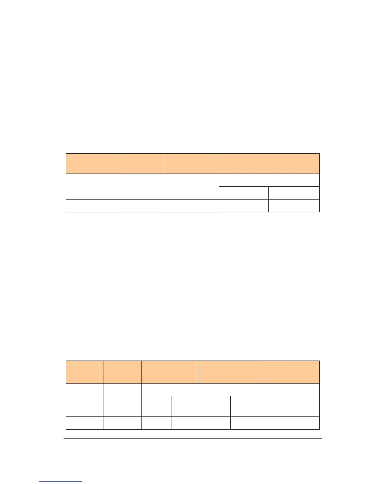
Table A.5 Slave error response message of Command code 03H
Slave address
Command
code
Error code CRC code
2 bytes
1 byte 1 byte 1 byte
Low byte High byte
83H
1) Slave address and CRC code: See “A2.2”.
2) Command code: 83H. It is = 03H + 80H.
3) Error code. For detail see “A2.4 Error code”.
4) Example: Read upper limit frequency.
Master request message: 01 03 00 08 00 01 05 C8
Normal response message: 01 03 02 13 88 B5 12 (Suppose that current upper limit
frequency is 50 Hz)
Error response message: 01 83 03 01 31 (Suppose that read word number is altered
from 0001 to 0002)
A2.2.2 Write one word (2 bytes) — Command code 06H
1. Master request message
Table A.6 Format of master request message
Slave
address
Comman
d code
Communication
address
Write data
CRC code
2 bytes 2 bytes 2 bytes
1 byte 1 byte
High
byte
Low
byte
High
byte
Low
byte
Low
byte
High
byte
06H

Table of Contents

Question and Answer IconNeed help?

Do you have a question about the Qirod QD100 Series and is the answer not in the manual?

Qirod QD100 Series Specifications

General IconGeneral
BrandQirod
ModelQD100 Series
CategoryDC Drives
LanguageEnglish

Summary

BASIC OPERATION AND TRIAL RUNNING

Parameter Setting Mode

Guides users on how to access and change inverter parameters.

Switching on and confirmation of display status

Pre-operation checks and confirmation steps before powering on.

DETAILED PARAMETER DESCRIPTION

Basic parameter group

Covers fundamental parameters for inverter operation.

Motor and its protection parameter group

Parameters related to motor configuration and protection settings.

Motor control parameter group

Parameters for fine-tuning motor control characteristics.

Fault protection parameter group

Parameters related to fault detection and protection functions.

Process PID parameter group

Covers additional PID control parameters and configurations.

FAULT DIAGNOSIS AND MEASURES

Fault code, cause and measures

Lists fault codes, their causes, and troubleshooting steps.

Description of alarm and indication code

Explains various alarm and indication codes displayed by the inverter.

APPENDIX A: SERIAL COMMUNICATION