125
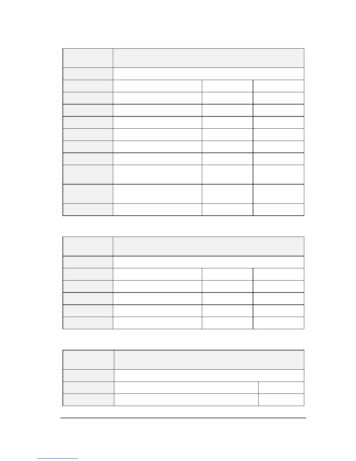
Table A.15 Logic input state monitoring
Communicatio
n address
Description of function
FE11 Logic input state monitoring
Bit Description 0 1
0 Terminal L1 OFF ON
1 Terminal L2 OFF ON
2 Terminal L3 OFF ON
3 Terminal L4 OFF ON
4 Terminal L5 OFF ON
5 Terminal L6 OFF ON
6
Terminal L7 or As Al1 during
logic input
OFF ON
7
Terminal L8 or As Al1 during
logic input
OFF ON
8-15 Reserved - -
Table A.16 Logic Output state monitoring
Communicatio
n address
Description of function
FE11 Logic output state monitoring
Bit Description 0 1
0 Terminal LO-CLO OFF ON
1 Relay T2 OFF ON
2 Relay T1 OFF ON
3-15 Reserve - -
Table A.17 Fault monitoring
Communication
address
Description of function
FC39 Fault monitoring
Value Corresponding fault Panel display
 Loading...