B-SERIES INSTALLATION, OPERATION AND SERVICE MANUAL
90 of 147
17.6 Additional Control Wiring
Depending on the style of the air handler (MUA, FR,
AM or VAV), there may be additional control wiring
that will be factory installed when the air handler is
ordered. Any additional control wiring that is added to
the air handler will be on the supplemental option
sheet. On the MUA style, there are no additional
controls unless an optional feature is added. The FR
style air handler uses a fixed damper and also does
not require additional control wiring unless an
optional feature is added.
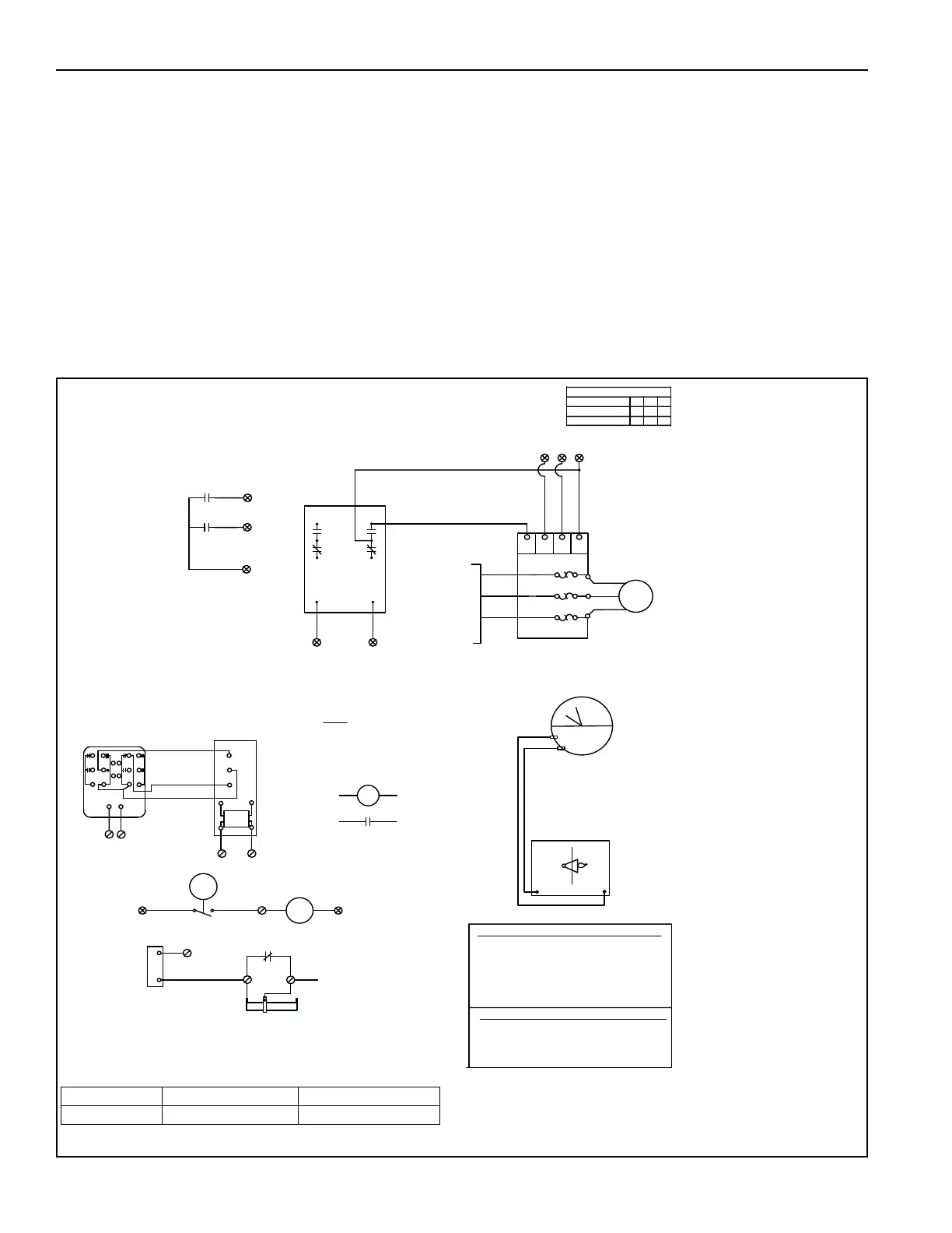
The VAV style air handler controls a floating damper
and a variable frequency drive (VFD) and requires
additional control wiring. For additional VAV style
wiring for models 2010 and 2010B, See Page 90,
Figure 48 and Page 92, Figure 50. For additional
VAV style wiring for models 2020 and 2030, See
Page 91, Figure 49 and Page 93, Figure 51 through
Page 95, Figure 53.
The AM style air handler controls a floating damper
and requires additional control wiring. For additional
AM style wiring for models 2010 and 2010B, See
Page 96, Figure 54. For additional AM style wiring for
models 2020 and 2030, See Page 96, Figure 55.
FIGURE 48: Additional Control Wiring for VAV Style (2010 and 2010B)
PHOTOHELIC (1) LOCATED INSIDE CONTROL ENCLOSURE
CONTROLS DIFFERENTIAL PRESSURE
ACROSS BURNER
2
RELAY
R1
MOTOR
OL
VFD
AIR HANDLER
MOTOR
T1
T2
T3
S1
B
C
L1
L2
L3
A
OL
OL
TO FUSABLE
DISCONNECT
3D
50
52
51
50
52
53
50
53
52 50
VARIABLE AIR VOLUME CONTROLLED BY THE DDC
P/N VAV - DDC
PRESET AT 0.75 (LOW) AND 0.90 (HIGH)
OVERLOAD AND M1
AUXILIARY CONTACT
IS REPLACED
WITH RM1 RELAY.
RM1
RM1
2
4
3D
3A
VFD PROGRAM PARAMTERS 25HP OR LESS
S4
SC
S3
S5
SN
S3
UP TO 25HP
30HP AND UP
B
C
A
VFD TERMINALS
VFD PROGRAM PARAMTERS 30HP OR MORE
B1-02=1, C1-01=25, C1-02=25
D2-02=50, D4-01=1
E1-01=VOLTS, E2-01=AMP
H1-03=10, H1-05=11
C1-01=20 ACCEL TIME (SEC)
C1-02=20 DECEL TIME (SEC)
d2-02=50% MINIMUM HZ (50%=30HZ)
H1-03=10, H1-04=11, H1-05=0F
H1-07=0F (V1000 ONLY)
L2-01=1, L5-01=5
ACCEL
DECEL
ACCEL/DECEL
CONTACTS
WIRED BY
OTHERS
1
2
4
(L1)
(L2)
HIGH
LOW
B
60
120V
61
W
R
62
2
MODU-
LATING
DAMPER
MOTOR
NOTE: MOTOR STARTER,
L1
L2
T1
T2
20VA
MODULATING
REGULATING
VALVE
REDUCED FLOW SWITCH
49A
48
R4B
49
NC
C
29
2
R4B
1
Damper Switch
DM2
0
1.0
1.0
PHOTOHELIC
PROFILE PLATE
PRESSURE
PROFILE PLATE
BEFORE
AFTER
PHOTOHELIC PNEUMATIC DIAGRAM
+
-
BURNER
Part Number Description Models
VAV VAV Control Wiring 2010 and 2010B