B-SERIES INSTALLATION, OPERATION AND SERVICE MANUAL
70 of 147
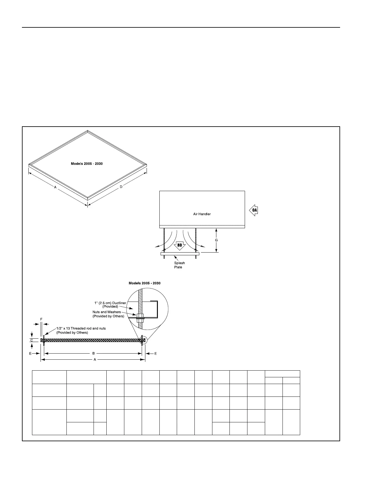
14.2 Splash Plate Installation
The splash plate is designed to hang directly from a horizontal air handler with a bottom discharge. Before
the splash plate can be installed on the air handler, first drill four holes (2005 - 2030) in the air handler floor.
These holes should be approximately 5/8" (15.9 mm) in diameter to accommodate 1/2" hanger rods
(supplied by others). These holes should be located as shown in the diagram on Page 71, Figure 31.
To attach all of the hanger rods to the splash plate, start by threading a flanged nut onto each hanger rod.
Then, slip each hanger rod down through a hole located in each corner of the splash plate. Next, feed a
flanged nut onto the rod below the splash plate See Page 70, Figure 30. The hanger rods should be attached
to the air handler in the same manner as the splash plate, with a flanged nut on both sides of the air handler
floor. Adjusting the nuts will level the splash plate. Torque hardware after leveling.
FIGURE 30: Splash Plate
Part NumberModel ABCDEF
G
(min)
G
(max)
H
Weight
lbs kg
77354.301[W] 2005
(in)
(cm)
22.0
55.9
19.5
49.5
0.9
2.2
25.0
63.5
1. 3
3.2
0.6
1. 6
15.0
38.1
20.0
50.8
N/A 20.0 9.1
77053.301[W]
2010/
2010B
(in)
(cm)
44.0
118. 8
41.5
105.4
0.9
2.2
44.0
111. 8
1. 3
3.2
0.6
1. 6
18.0
47.5
27.0
68.6
N/A 40.0 18.1
77253.301[W]
2020
(in)
(cm)
54.8
139.1
51.3
130.2
1. 8
4.4
54.8
139.1
1. 8
4.4
0.8
2.0
25.0
63.5
38.0
96.5
N/A
60.0 27.2
2030
(in)
(cm)
30.0
76.2
45.0
114. 3
N/A