B-SERIES INSTALLATION, OPERATION AND SERVICE MANUAL
42 of 147
11.4.1 Filter Section Support Assembly Installation (2010 - 2030)
It is best to assemble the support base and support arms to the filter section prior to attaching the filter
section to the air handler but can also be assembled to a previously installed filter section. Refer to Page 42,
Figure 22.
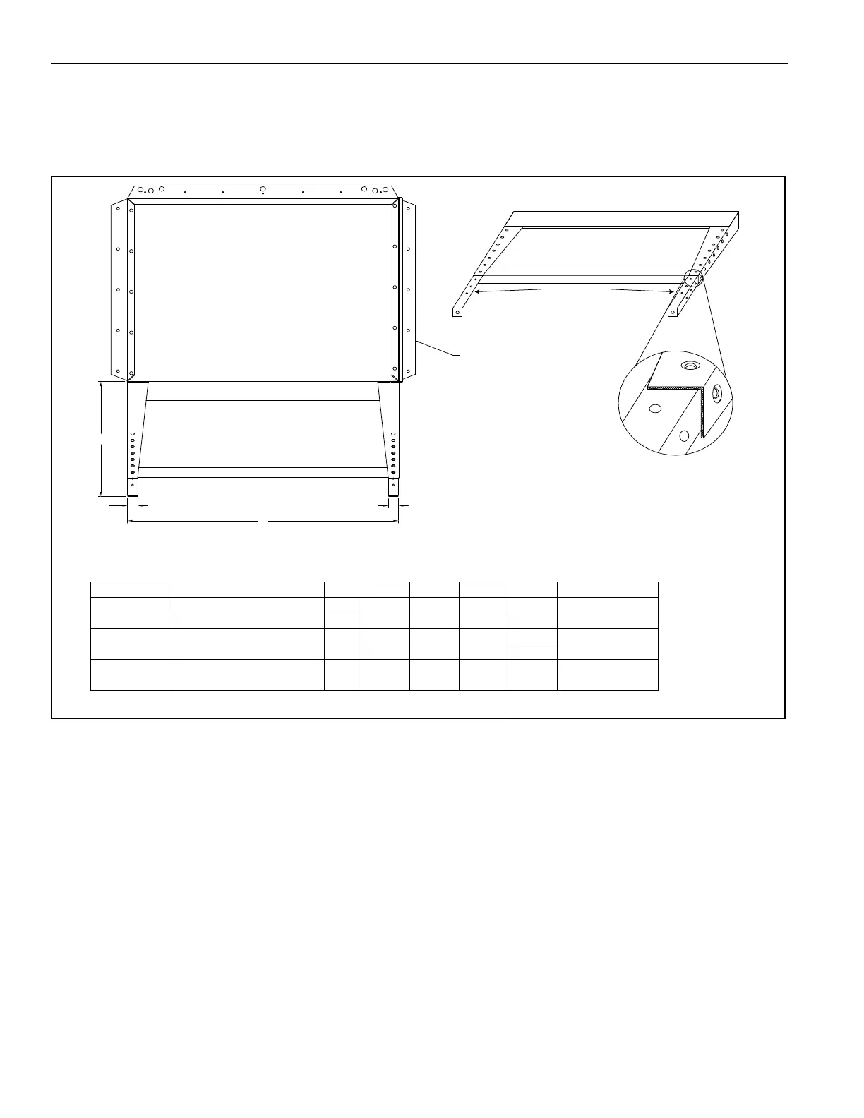
FIGURE 22: Filter Section Support Assembly
Step 1: Place the support base (P/N 7740800X) up to the bottom of the filter section towards the inlet end
and line up the pre-drilled holes. Use TEK self-tapping screws (P/N 13404) in the middle of the support base
(P/N 7740800X) to secure the support base in place.
Step 2: Line up the pre-drilled holes at the ends of the support base, the filter section and the support legs
(P/N 7740900X) and attach the legs to the bottom of the filter section through the support base with TEK self-
tapping screws (P/N 13404). Install TEK self-tapping screws (P/N 13404) at each of the remaining hole
locations in the support base.
Step 3: Mount the filter section to the air handler as described on Page 43, Section 11.5.
Step 4: Line up the support extension (P/N 77410001) with the left support leg (P/N 77409001) and select the
appropriate height alignment. Attach the support extension and left support legs and support brace
(P/N 774110X) at the lowest overlap position with one ¼-20 bolt (P/N 20483) and flange nut (P/N 220630) on
the front surface. Install a second ¼-20 bolt (P/N 20483) and flange nut (P/N 220630) directly above the first,
securing all three parts together.
Repeat step 4 on the right side of the su
pport assembly.
Support Leg
Left Side
Support Leg
Right Side
Support Base
Extension Arm
Left Side
Support Extension
Cross Brace
NOTE: 1) CONTRACTOR/INSTALLER MUST MAKE
APPROPRIATE ALLOWANCES FOR DUCT
CONNECTIONS.
2) SUPPORT LEG IS REQUIRED WHEN A FILTER
SECTION AND INLET HOOD ARE ORDERED.
A
CC
B
FILTER SECTION
3) SUPPORT LEG IS PROVIDED FOR USE WITH
STANDARD 19" (50 cm) ROOF CURB. SUPPORT
LEG FOR USE WITH STANDARD 46" (116.8 cm)
LEGS PROVIDED BY OTHERS.
Model Part Number A Min A Max B C Weight lbs (kg)
2010 and
2010B
77412.001
in 16.0 24.0 38.8 1.5
16 (7.3)
cm 40.5 60.8 98.4 3.7
2020 77412.002
in 16.0 24.0 49.6 1.5
18 (8.2)
cm 40.5 60.8 126.0 3.7
2030 77412.003
in 16.0 24.0 64.1 1.5
20 (9.1)
cm 40.5 60.8 162.7 3.7