B-SERIES INSTALLATION, OPERATION AND SERVICE MANUAL
24 of 147
SECTION 9: LEGS
Part numbers that end with a “[W]” indicate that the
part can be ordered with either an unpainted
galvanized finish or an acrylic modified alkyd enamel
finish. To order with a galvanized finish, do not
include the "W" at the end of the part number; to
order with a painted finish, include the "W" at the end
of the part number.
9.1 Leg Mounting
Legs can be used when mounting an air handler on a
concrete slab or directly on the floor. Legs are
available for all models in the horizontal
configuration.
9.2 Leg Mounting - Horizontal Air Handler
(2005 - 2030)
The 46" (116.8 cm) legs must first be mounted to the
air handler before being mounted to the concrete
slab or floor. To attach the legs with the air handler
must first be lifted with the provided lifting lugs. See
Page 17, Section 6.1 for safe lifting practices. In each
corner of the bottom of the air handler, four leg-
mounting holes will be found. See Page 24, Figure
17.
The legs can now be mounted one at a time to the
inside of the corner by removing the hard
ware that
occupies each of the bolt locations. Place the leg on
the inside of the corner and attach with the previously
removed hardware. Missing hardware needs to be
added at each bolt location. The required hardware is
a 5/16"-18 x 1" grade 5 bolt, a 5/16" flat washer, and
a 5/16"-18 grade 5 flange nut.
On models 2020 and 2030, there is a bracket on the
inside of each corner that is held in place by the two
bolts closest to the corner. This bracket must be
removed when the leg is attached to the air handler.
Bracket can be discarded once legs are attached.
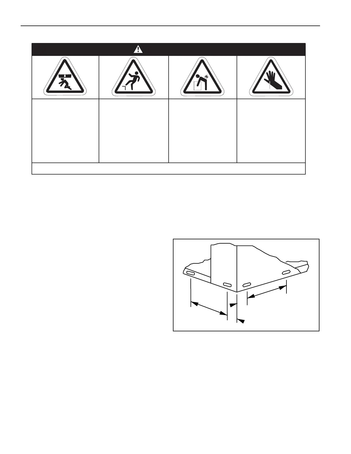
FIGURE 17: Leg Mounting Holes (2005 - 2030)
To attach the legs to a concrete slab, the base of
each leg is equipped with two 1" holes. Studs
capable of accepting 5/8" nuts must be installed in
the concrete slab. For stud positioning, See Page 25,
Figure 18.
The air handler may now be placed down over the
slab studs. The legs should then be bolted down with
5/8" nuts. See Page 25, Figure 19.
Crush Hazard
Use proper lifting
equipment and
practices.
Falling Hazard
Use proper safety
equipment and prac-
tices to avoid falling.
Severe Injury Hazard
Use proper lifting
practices and equip-
ment.
Equipment and
accessories are
heavy.
Cut/Pinch Hazard
Wear protective gear
during installation,
operation and
service.
Edges are sharp.
WARNING
Failure to follow these instructions can result in death, injury or property damage.
10"
(25.4 cm)
1.5"
(3.8 cm)
1.5"
(3.8 cm)
10"
(25.4 cm)