SECTION 19: START-UP PROCEDURES
117 of 147
Installation Code and Annual Inspections:
All installation and service of RAPID
®
equipment
must be performed by a contractor qualified in the
installation and service of equipment sold and
supplied by Rapid Engineering LLC and conform to
all requirements set forth in the RAPID
®
manuals and
all applicable governmental authorities pertaining to
the installation, service, labeling and operation of the
equipment.
To help facilitate optimum performance and safety,
Rapid Engineering LLC recommends that a qualified
contractor conduct, at a minimum, annual
inspections of your RAPID
®
equipment and perform
service where necessary, using only replacement
parts sold and supplied by Rapid Engineering LLC.
Check installation site to ensure all codes and
engineering specifications are correct. This section of
the manual is intended to be used as an instructional
guide to the commissioning of the direct fired air
handler. Fill out the start up sheet located at the back
of the manual as each step of the procedure is
performed. This procedure must be completed by the
commissioning contractor and returned to Rapid
Engineering LLC. If the document is not returned, the
manufacturing date will be used as the warranty start
date.
All components have been checked at initial factory
startup. During transit components may have
loosened/shifted, check all wiring before initial
startup.
19.1 Installation of Recirculating Air Handler
Every direct-fired air handler which recirculates room
air (i.e., AM and FR styles) must utilize either a
control system which limits temperature rise in
proportion to the amount of ou
tdoor air, or a room
carbon dioxide sensor, installed per the
manufacturer’s recommendations. The normally-
closed contacts of this sensor must be wired in as
per the CO
2
interlock diagram, maintaining the room
concentration of CO
2
below 5,000 ppm. Select the
CO
2
interlock diagram based on air handler
configuration and model. See Page 97, Figure 56
through Page 97, Figure 58.
With the AM and VAV package, a temperature rise
limiting resistor comes prewired. See Page 90,
Figure 48 through Page 96, Figure 55. When the air
handler goes into full recirculation, the resistor is
activated, lowering the maximum temperature rise to
comply with government standards. For the FR
package, the gas valve is preset to the proper
temperature rise. See Page 121, Table 24.
19.2 Mechanical
This piece of equipment requires at least 4 CFM
(6.8m
3
/h) of outside air per 1,000 Btu/h (0.293 kW).
Before installation, check that the local distribution
condition, nature of gas and pressure, and the
current state of adjustment of the equipment are
compatible.
If filters are not installed (via inlet hood or filter
section), an air strainer must be installed on the inlet
of the air handler with openings less than or equal to
5/8" (16 mm) in diameter.
Air inlets must be installed with the lowest edge 19"
(500 mm) above any surface. This applies to roof
curbs, upright stands and suspended air handlers.
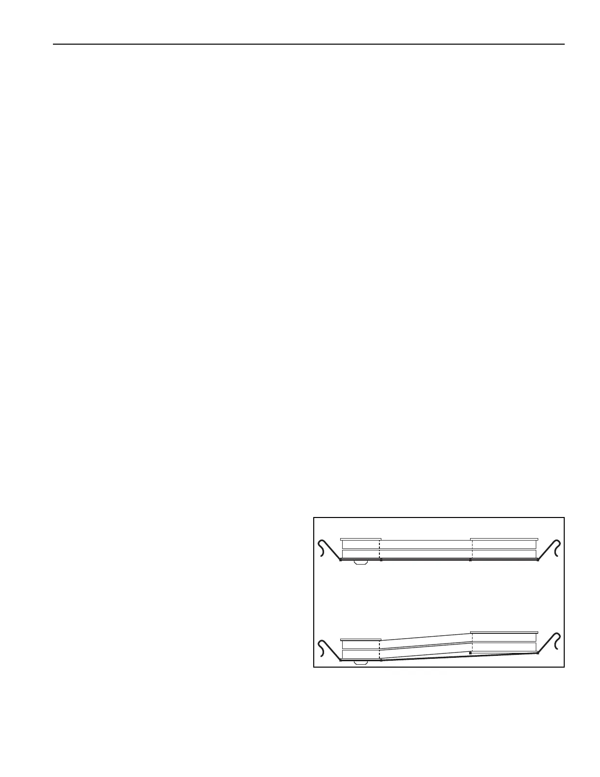
19.2.1 Sheave Alignment
Sheaves are factory aligned. On all air handlers,
check sheave alignment as follows.
1. Attach a string to the vertical surface next to
the blower shaft bearing. (See Page 117, Figure
76)
2. Wrap the string around the blower sheave and
across both sheave surfaces as shown.
3. Adjust until all four contact points (triangle)
touch the sheave s
urfaces. "IN" or "OUT"
adjustment of the motor sheave and/or motor
adjustment may be required.
4. Pull the string away from the motor sheave and
then move it slowly back towards the sheave,
making sure the string remains straight while
touching all contact points.
5. Remove string before turning air handler on.
FIGURE 76: Sheave Alignment
Correct Alignment
Incorrect Alignment