B-SERIES INSTALLATION, OPERATION AND SERVICE MANUAL
80 of 147
(pilot stays lit during burner operation). Models 2020
- 2030 operate with interrupted pilot (pilot turns off
after flame is established). The flame sensor
observes main flame only.
Model 2005 uses a flame rod to detect the flame
(minimum flame current 1µA); Models 2010 - 2030
use an ultraviolet (UV) light scanner (5.0 Vdc flame
signal).
If a pilot flame is not present, the electrical signal
cannot be sent and the pilot burner gas valve will
close. The relay is equipped with a 10-second trial for
ignition. If ignition does not occur, the flame
safeguard relay will lockout, and must be manually
reset. 2005 will reset upon power restoration. (See
the Trouble-Shooting Guide - Page 136, Section 22)
17.5.5 Discharge Temperature Sensor
This device senses the discharge temperature of the
air at the blower. The discharge temperature sensor
reports the discharge temperature to the temperature
control amplifier which modulates the burner to the
temperat
ure set on the remote panel selector. Should
this system fail, the manual high temperature limit
switch will turn the burner off. BMS-ready air
handlers do not come equipped with this sensor and
must be field-supplied.
17.5.6 Positive Low Fire Start
This feature forces the burner to start in low fire
rather than high fire during the air handler’s start-up
sequence of operations. The burner maintains its low
fire setting for 10 seconds (as per timer setpoint)
before it begins to modulate.
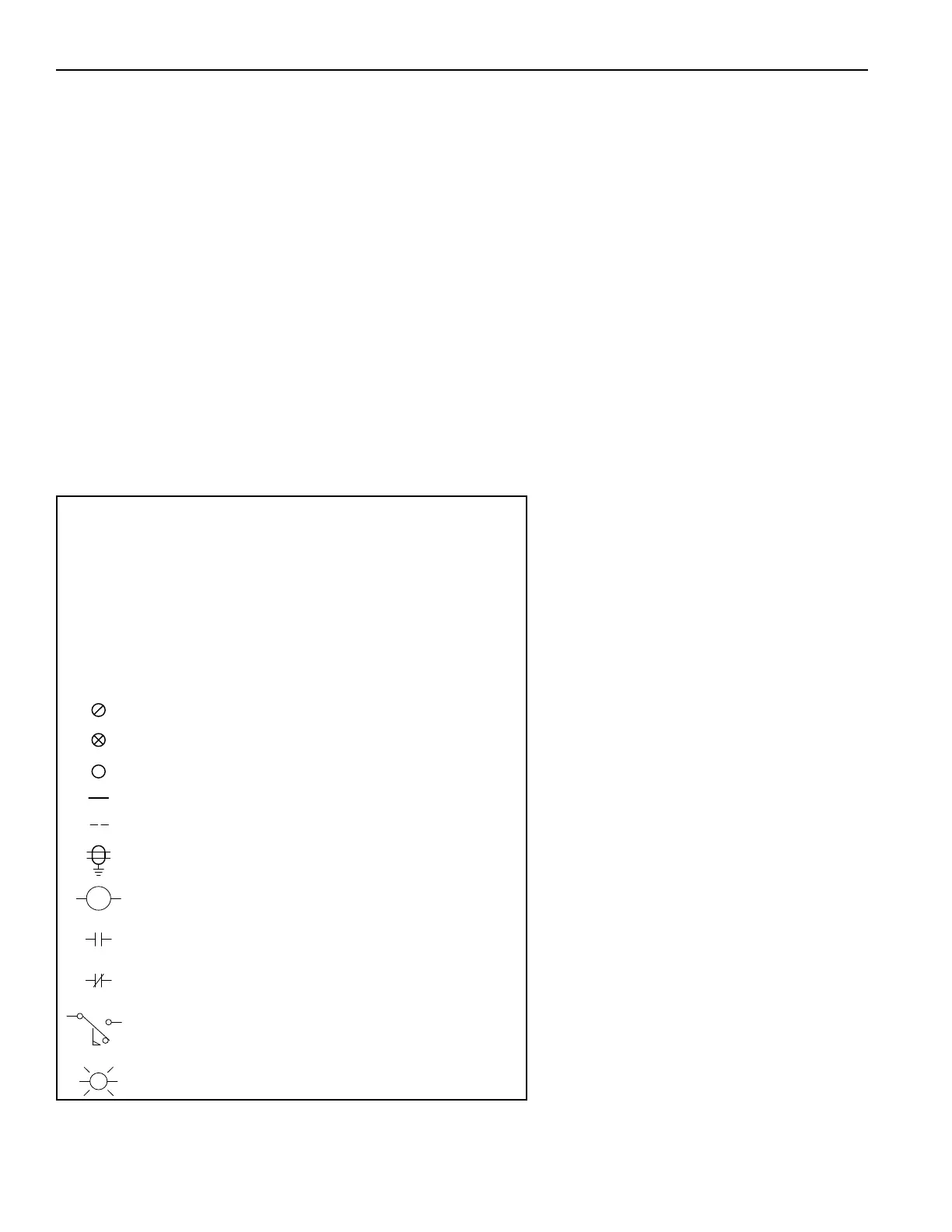
FIGURE 38: Wiring Diagram Key
Notes:
1. Wire Over 24vac To Be A Minimum Of
16 Awg Flexing Type Mtw, 105c, 600v Or Equivalent
Colors 115vac: Phase-red, Neutral-white,
Ground-green
Colors 24vac: Blue
2. Control Wire To Be A Minimum Of 20 Awg Type
Belden 5401fe Cmr 75c Shielded Or Equivalent
3. Power Supply And Motor Wires To Be Sized To Nfpa79,
Latest Edition
Colors All Voltages: Phase(s)-black, Ground-green
Terminals Located In Control Panel Only
Terminals Located In Control Panel And
Connected To The Remote Panel
Terminals Located In Remote Panel Only
Wire(s) Located In Control Panel
Wire(s) Located In Remote Panel
Shielded Wire(s), One End Grounded
M1
CR2
C
No
Nc
Relay / Motor Starter Coil (Associated With M1 Contacts)
Normally Open Contact (Associated With M1 Coil)
Normally Closed Contact (Associated With CR2 Coil)
Air Flow Switch
Indicator Light On Remote Panel
M1
L