SECTION 17: ELECTRICAL
97 of 147
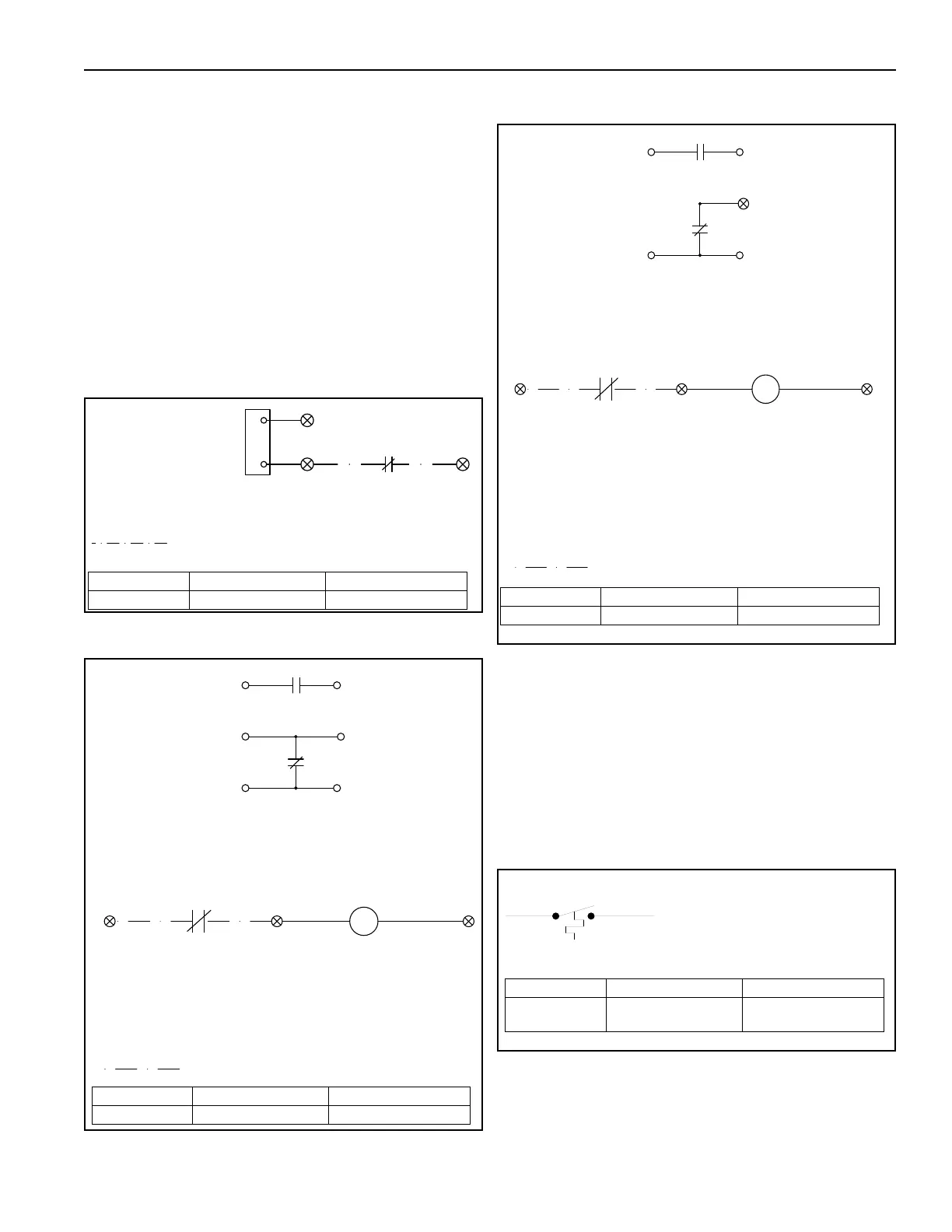
17.7 Carbon Dioxide Interlocks
All air handlers that recirculate air from the heated
space require either a control to limit the temperature
rise in proportion to the amount of outdoor air or the
use of a room carbon dioxide sensor. The carbon
dioxide sensor is field provided and set to maintain a
CO2 concentration below 5,000 ppm. For the
additional wiring to accommodate this requirement
for the FR and MUA style air handler, See Page 97,
Figure 56. For the additional wiring to accommodate
this requirement for the AM and VAV style air
handlers See Page 97, Figure 57 for 2010 and 2010B.
See Page 97, Figure 58 for models 2020 and 2030.
FIGURE 56: CO2 Sensor Interlock for FR and
MUA Style
FIGURE 57: CO2 Sensor Interlock for AM and VAV
Style (2010 and 2010B)
FIGURE 58: CO2 Sensor Interlock for AM and VAV
Style (2020 and 2030)
17.8 Control Options
17.8.1 Mild Weather Outside Air Stat
This option is designed to turn the burner off when
the incoming outside air is at or above the
temperature setpoint. The blower is allowed to run for
continued ventilation. The mild weather outside air
stat is located in the control enclosure. It has an
adjustable setting between -20° F (-29° C) and
100° F (38° C).
49
48
CO2 Sensor
49A
NC C
Located On The Main Diagram
CO2 Sensor Wiring By Others
Modulating
Regulating
Valve
This Replaces The MRV Wiring
Part Number Description Models
13205105 CO2 Sensor Interlock FR and MUA
CO2 Sensor Wiring By Others
2
CO2 Sensor
Pressure
Building
W
B
Modulating
Damper Motor
Switch or
Photohelic
CR7
CR7
CR7
63
Operation:
Damper Is Forced Into 100% Outside Air Until
CR7 Is Energized By The CO2 Sensor
Allowing The Damper To Modulate
When The CO2 Sensor Reaches The Set Point
The Sensor Contacts Will Open Deenergizing CR7
1
Relay CR7 Connections Are Located Between The
Damper Motor And The Building Pressure Switch or Photohelic
L
H
61
60
62
R
Part Number Description Models
13205106 CO2 Sensor Interlock 2010 and 2010B
CO2 Sensor Wiring By Others
2
CO
2
Sensor
Pressure
Building
L3
L2
Modulating
Damper Motor
Switch or
Photohelic
CR7
CR7
CR7
63
Operation:
Damper Is Forced Into 100% Outside Air Until
CR7 Is Energized By The CO2 Sensor
Allowing The Damper To Modulate
When The CO2 Sensor Reaches The Set Point
The Sensor Contacts Will Open Deenergizing CR7
1
Relay CR7 Connections Are Located Between The
Damper Motor And The Building Pressure Switch or Photohelic
L
H
1
60
62
60A
62A
Part Number Description Models
13205106 CO2 Sensor Interlock 2020 and 2030
OA STAT
9 9A
RED BLUE
SET AT 85° F (29° C)
MOUNTED AT PROFILE PLATE
TO TEST: SET DIAL TO MAX TEMP
UNIT OPERATES
SET DIAL TO MIN TEMP
UNIT SHUTS DOWN
Part Number Description Models
80930
Mild Weather
Outside Air Stat
All Models