SECTION 19: START-UP PROCEDURES
121 of 147
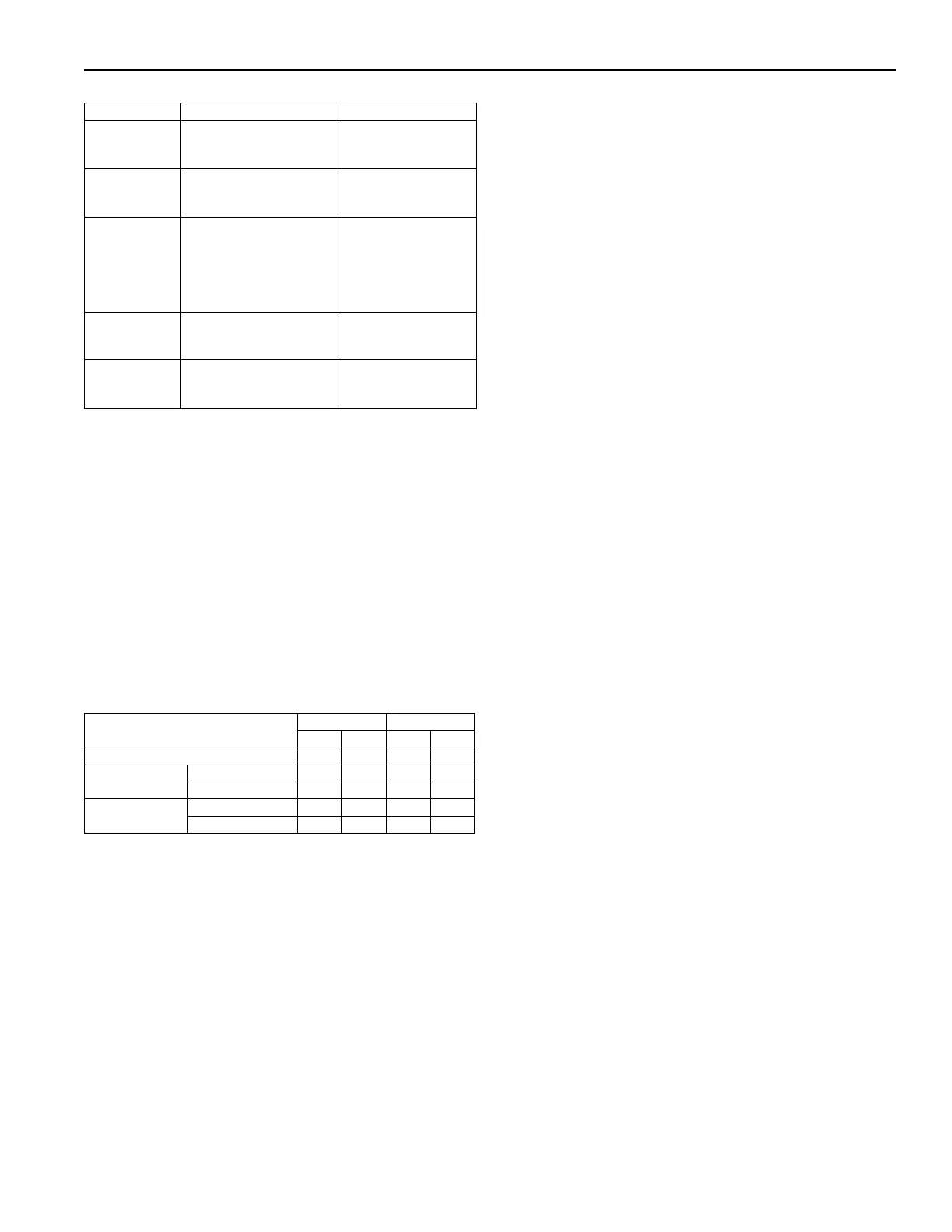
Table 23: Burner Mode by Amplifier Type
19.6 Safety Shut Off Valve Check
After the initial start up and gas pressure adjustment,
verify gas soundness of each SSOV (Safety Shut Off
Valve). This check must be repeated after the first
100 hours of operation.
19.7 Temperature Control System Calibration
The temperature control system components are
factory calibrated to a base resistance so that
component replacement will not upset the system
calibration. If the temperature control system should
require field calibration, refer to the provided
temperature control amplifier product information
sheet.
Table 24: Maximum Temperature Rise
* Also applies to VAV style at minimum airflow.
Amplifier Type High Fire Mode Low Fire Mode
Series 14
Remove wire #45 from ter-
minal #4 on the amplifier
Remove wire #16 from
terminal #8 on the
amplifier
Series 44
Remove wires #40 and #45
from terminals #2 and #4
on the amplifier
Remove wire #16 from
terminal #9 on the
amplifier
SC11 Signal
Conditioner
Set BMS to max fire or
remove input wires #40 and
#41 from terminals #6 and
#5 and connect a 9VDC
battery to the signal condi-
tioner
Remove wire #16 from
terminal #1 on the
signal
Series 94
Disconnect selector ribbon
cable from the amplifier.
Remove wire #16 from
terminal #2 on the
amplifier
Series MP2
Set system to maximum
temperature
Remove wire #16 from
terminal #2 on the
amplifer
Model
Natural Gas LPG
°F °C °F °C
2005 90 50 70 38.9
2010 - 2010B
Non-Recirculating* 100 55 80 44.5
Recirculating 49 27.2 42 23.4
2020 - 2030
Non-Recirculating* 100 55 80 44.5
Recirculating 73.5 40.8 63 35