B-SERIES INSTALLATION, OPERATION AND SERVICE MANUAL
66 of 147
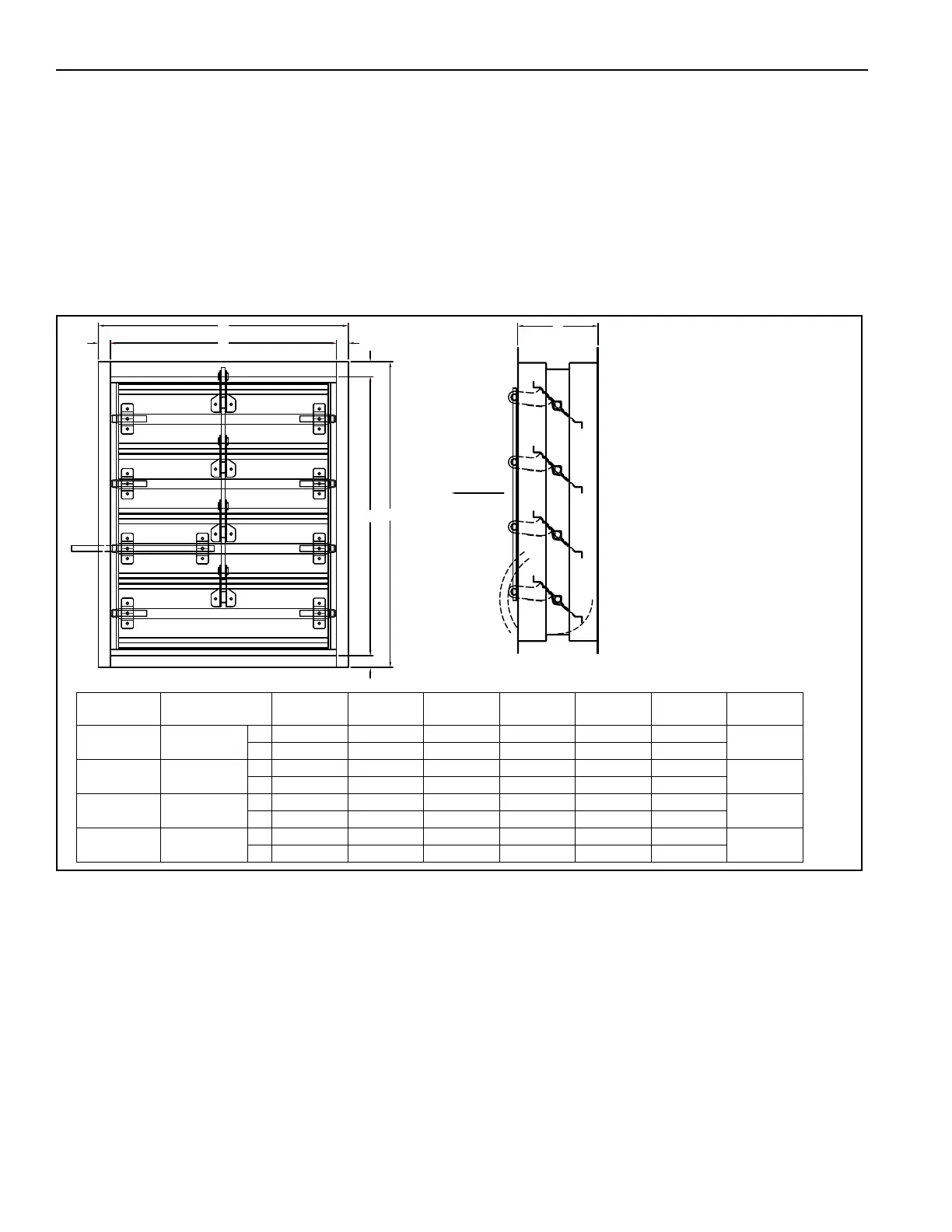
13.1 Discharge Damper
Discharge dampers are shipped loose. Discharge dampers are designed to be mounted downstream of the
air handler in ductwork. A qualified contractor/installer must make appropriate allowances for duct
connections.
To install the discharge damper on an interior wall, drill holes every 8" (20.5 cm) in the flanges on all four
sides of the discharge damper to accommodate lag bolts (provided by others).
Discharge dampers are not recommended to be mounted directly to the air handler.
FIGURE 26: Motorized Discharge Damper (2005 - 2030)
C
E
C
D
A
B
C
C
F
NOTE:1) CONTRACTOR/INSTALLER MUST MAKE
APPROPRIATE ALLOWANCES FOR DUCT
CONNECTIONS.
2) NUMBER OF LOUVERS WILL VARY.
3) MOUNTED DOWNSTREAM OF AIR HANDLER IN
DUCT WORK. DOES NOT MOUNT DIRECTLY TO
AIR HANDLER. FIELD WIRED TO PROVIDED
TERMINALS ON CONTROL PANEL.
AIR FLOW
Model Part Number A B C D E F
Weight lbs
(kg)
2005 77014.301
in 21.0 19.0 1.0 19.0 17.0 9.0
40 (18.1)
cm 53.3 48.3 2.5 48.3 43.2 22.9
2010/
2010B
77018.301
in 27.0 25.0 1.0 23.5 21.5 8.0
60 (27.2)
cm 68.6 63.5 2.5 59.7 54.6 20.3
2020 80922.2
in 37.0 34.0 1.5 36.0 33.0 10.0
100 (45.4)
cm 94.0 86.4 3.8 42.0 83.8 25.4
2030 77537.2
in 42.0 39.0 1.5 42.0 39.0 10.0
150 (68)
cm 106.7 99.1 3.8 106.7 99.1 25.4