B-SERIES INSTALLATION, OPERATION AND SERVICE MANUAL
98 of 147
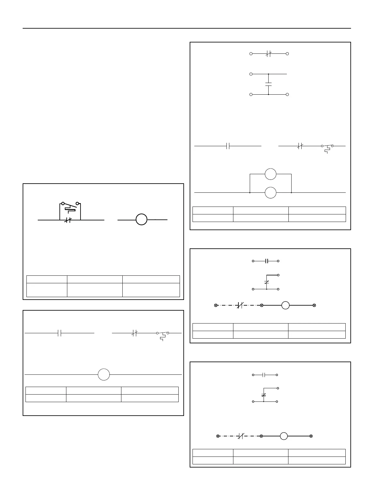
17.8.2 Low Temperature Limit with Override Timer
This option is designed to turn the unit off when air is
discharged below the temperature setpoint for a
period in excess of timer setpoint. The low
temperature limit switch is located in the air handler’s
control enclosure. The low temperature limit switch
has an adjustable setting between -20° F (-29° C)
and 100° F (38° C). The timer by-passes the low
temperature limit switch for the first 5 minutes to allow
the burner to establish a flame when the air handler
is turned on. If the air handler’s discharge
temperature falls to the predetermined low
temperature limit setpoint, after the 5 minute
establishing period, the air handler’s blower will be
turned off. To reset the low temperature limit switch,
set the fan switch to off and then on again. The air
handler will return to the normal sequence of
operations.
FIGURE 59: CO Sensor Interlock for FR and MUA
FIGURE 60: CO Sensor Interlock for AM and VAV
FIGURE 61: CO Sensor Interlock for AM and VAV
with Photohelic
FIGURE 62: CO Sensor Interlock for AM with
Building Pressure
LOW LIMIT SWITCH
2
3A
LT
RED YELLOW
3A
LT
3B
SET AT 5 MIN
SET AT 50° F (10° C)
LOW LIMIT TIMER
LOCATED AT DISCHARGE SIDE OF BLOWER
TO TEST:
SET DIAL TO MIN TEMP
UNIT OPERATES
SET DIAL TO MAX TEMP
UNIT SHUTS DOWN
Part Number Description Models
01003
Low Temperature Limit
with Override Timer
All Models
CR5
WIRED BY OTHERS 2
CR5 CR5
1
3A
7
7A
HI TEMP
LIMIT
HLS
MANUAL
RESET
8
Part Number Description Models
13205103 CO Interlock All Models
PRESSURE
BUILDING
60
62
61
L
H
MODULATING
DAMPER MOTOR
SWITCH
CR6
CR6
CR5
WIRED BY OTHERS 2
CR5 CR5
1
3A
7
7A
CR6
SET TO
0.01" W.C.
HI TEMP
LIMIT
HLS
MANUAL
RESET
8
62A
Part Number Description Models
13205104 CO Interlock All Models
2
CO2 SENSOR
60
62
1
MODULATING
DAMPER MOTOR
PHOTOHELIC
CR7
CR7
CR7
631
62A
Part Number Description Models
13205106 CO Sensor 2020 and 2030
2
CO2 SENSOR
PRESSURE
BUILDING
60
62
MODULATING
DAMPER MOTOR
SWITCH
CR7
CR7
631
RELAY CR7 CONNECTIONS ARE LOCATED BETWEEN THE
DAMPER MOTOR AND THE BUILDING PRESSURE SWITCH
L
H
1
62A
Part Number Description Models
13205106 CO Sensor 2020 and 2030