SECTION 17: ELECTRICAL
99 of 147
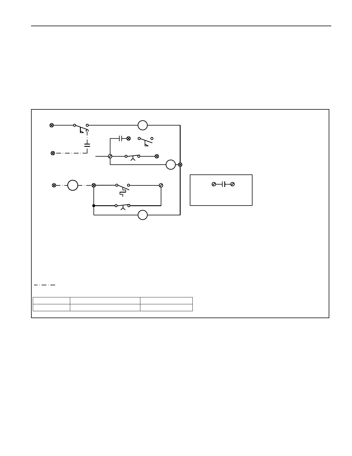
17.8.3 MUA / Exhaust Failsafe Interlock
This option incorporates the low temperature limit
with override timer and an exhaust fan airflow switch
monitor. The exhaust fan airflow switch is field
provided and field wired as per the option sheet
supplied with the unit. When the air handler is turned
on there is a 5 minute establishing period for the low
temperature limit switch and the exhaust fan
interlock. If the air handler’s discharge temperature
falls to the predetermined low temperature limit
setpoint, after the 5 minute establishing period, the
air handler fan will be turned off. If there is a failure of
the exhaust fan to activate the field supplied airflow
switch, after the 5 minute establishing period, the air
handler fan will be turned off. To reset the
MUA/exhaust failsafe interlock, set the fan switch to
off and then on again. The air handler will return to
the normal sequ
ence of operations.
3C
AFS-3
TD5
TIMING RELAY
TD5
21
3D
CR3
CR3
LOW PRESSURE
SWITCH 0.3 in. w.c.
20
CONTROL RELAY
AIR FLOW SWITCH
2
3B
LIMIT
TAS-3
LOW TEMP
TIMING RELAY
TD6
TD6
3A
SET AT 5 MIN
SET AT 5 MIN
AIR FLOW SWITCH
EXHAUST FAN
RED YELLOW
-AFS-3: FIELD LOCATE ON EXHAUST FAN, SWITCH PROVIDIED BY OTHERS
-LOW TEMP LIMIT LOCATED AT DISCHARGE SIDE OF BLOWER
-TO TEST:SET DIAL TO MIN TEMP UNIT OPERATES
SET DIAL TO MAX TEMP UNIT SHUTS DOWN
NOTE: -LOW PRES. SWITCH (BETWEEN WIRES 1 AND 20) REPLACES
LOW PRES. SWITCH (BETWEEN WIRES 8 AND 8A)
-CR3 RELAY NORMALLY OPEN CONTACTS REPLACE LOW PRESSURE SWITCH
ON MAIN WIRING DIAGRAM (BETWEEN WIRES 8 AND 8A)
25A
25
CLOGGED FILTER WIRING FOR SDC (80010) AND DTC (80000)
REMOTE PANELS
CR4
CR4
2
CR3
8
8A
REPLACES LOW PRESSURE
SWITCH ON MAIN WIRING
1
xxxx
xx
xxxxxxxx
DIAGRAM
FIELD WIRED BY OTHERS
xxxxxxxxxxx
Part Number Description Models
01004 MUA/Exhaust Failsafe Inlock All Models